
Electric hair remover

a hair removal and electric technology, applied in the field of electric hair removal, can solve the problems of difficult to remove hair that is beyond the reach of the hand, difficult to make the body part telescopic, and difficult to reach, and achieve the effect of improving usability during operation

Inactive Publication Date: 2012-01-10
MATSUSHITA ELECTRIC WORKS LTD
View PDF16 Cites 10 Cited by
  • Summary
  • Abstract
  • Description
  • Claims
  • Application Information

AI Technical Summary

Benefits of technology

"The present invention provides an electric hair remover that can improve usability during operation. The electric hair remover includes a body part with a head end part and a blade part for cutting hair. It also has a holder part that can slide and rotate along the body part's longitudinal direction. This allows for easier removal of hair that is beyond the reach of hand or hard to reach."

Problems solved by technology

For receiving the motor, driver, battery block and the like in the body part, the above conventional electric hair remover, however, has difficulty in making the body part telescopic which also serves as a holder part.
In other words, the body part of the conventional electric hair remover is fixed at a relatively short length, making it difficult to remove hair which is beyond the reach of hand or hard to reach.

Method used


Image

  • Electric hair remover
  • Electric hair remover
  • Electric hair remover

Examples


Embodiment Construction

[0025]In the following, an embodiment of the present invention will be described in detail with reference to the accompanying drawings.

[0026]For ease of understanding, the following description will contain various directional terms, such as right, left, upper, lower, forward, rearward and the like. However, such terms are to be understood with respect to only a drawing or drawings on which the corresponding part of element is illustrated.

[0027]In addition, it is noted that the drawings referred to hereinafter as illustrating the preferred embodiment of the present invention are not to scale and are schematic in nature and, therefore, should not be taken too literally. Nevertheless, the drawings illustrate the invention sufficiently to enable one skilled in the art to practice the invention.

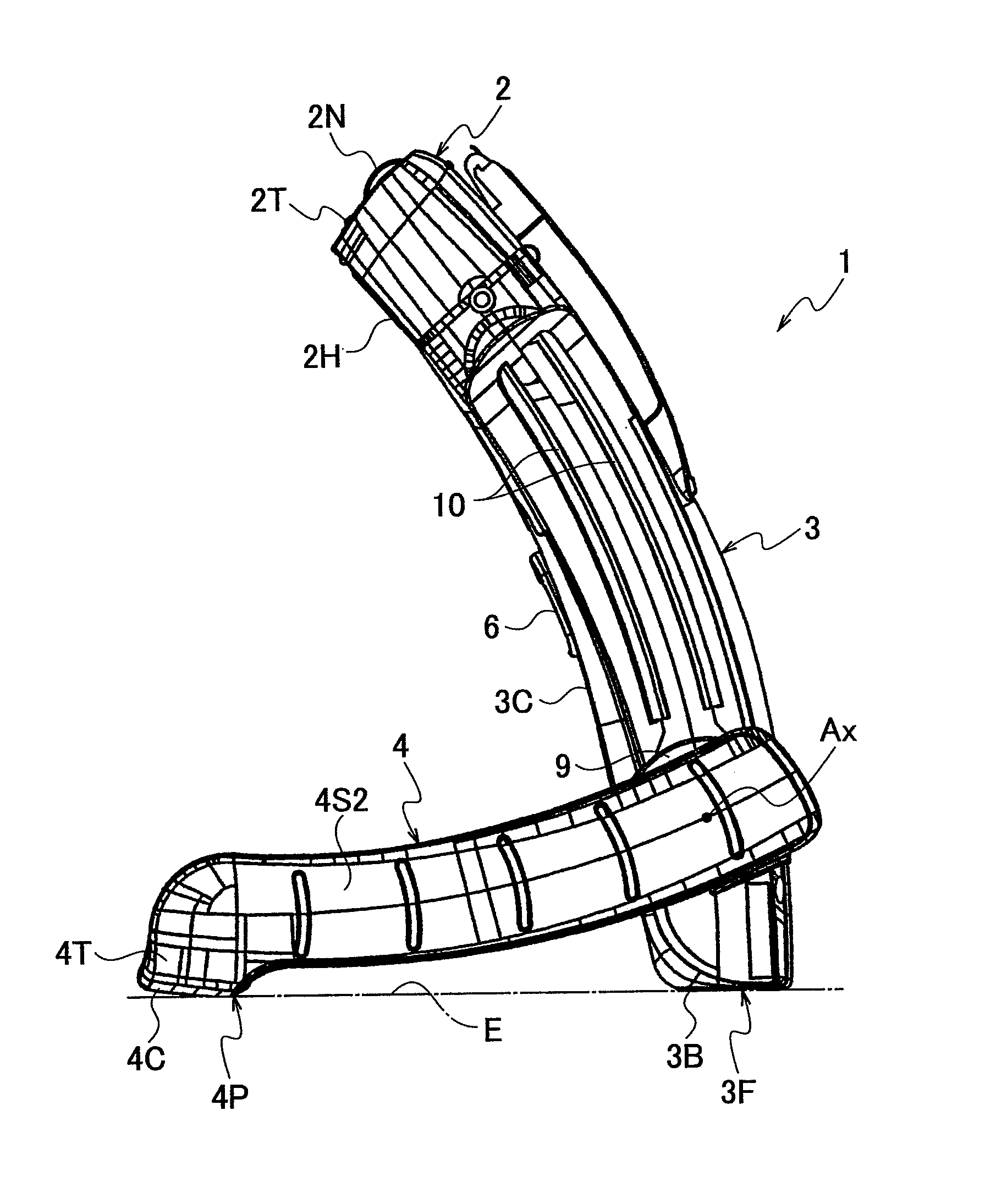
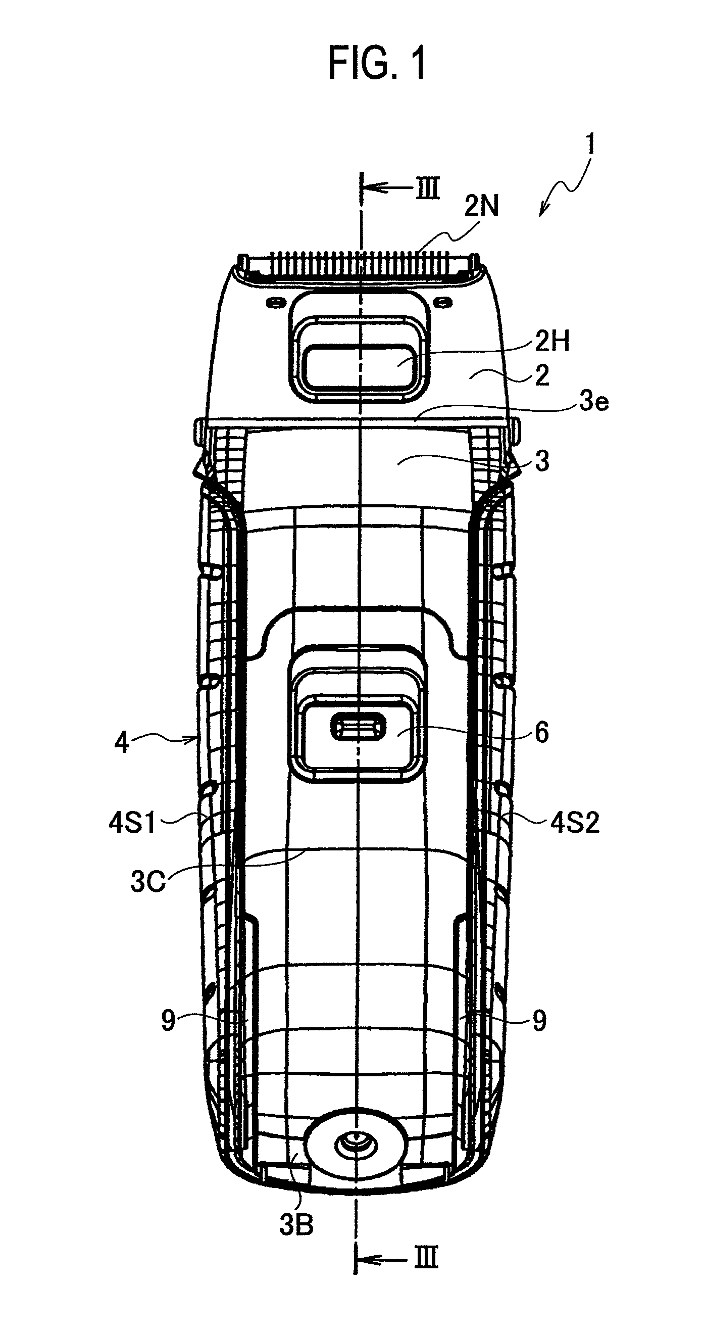
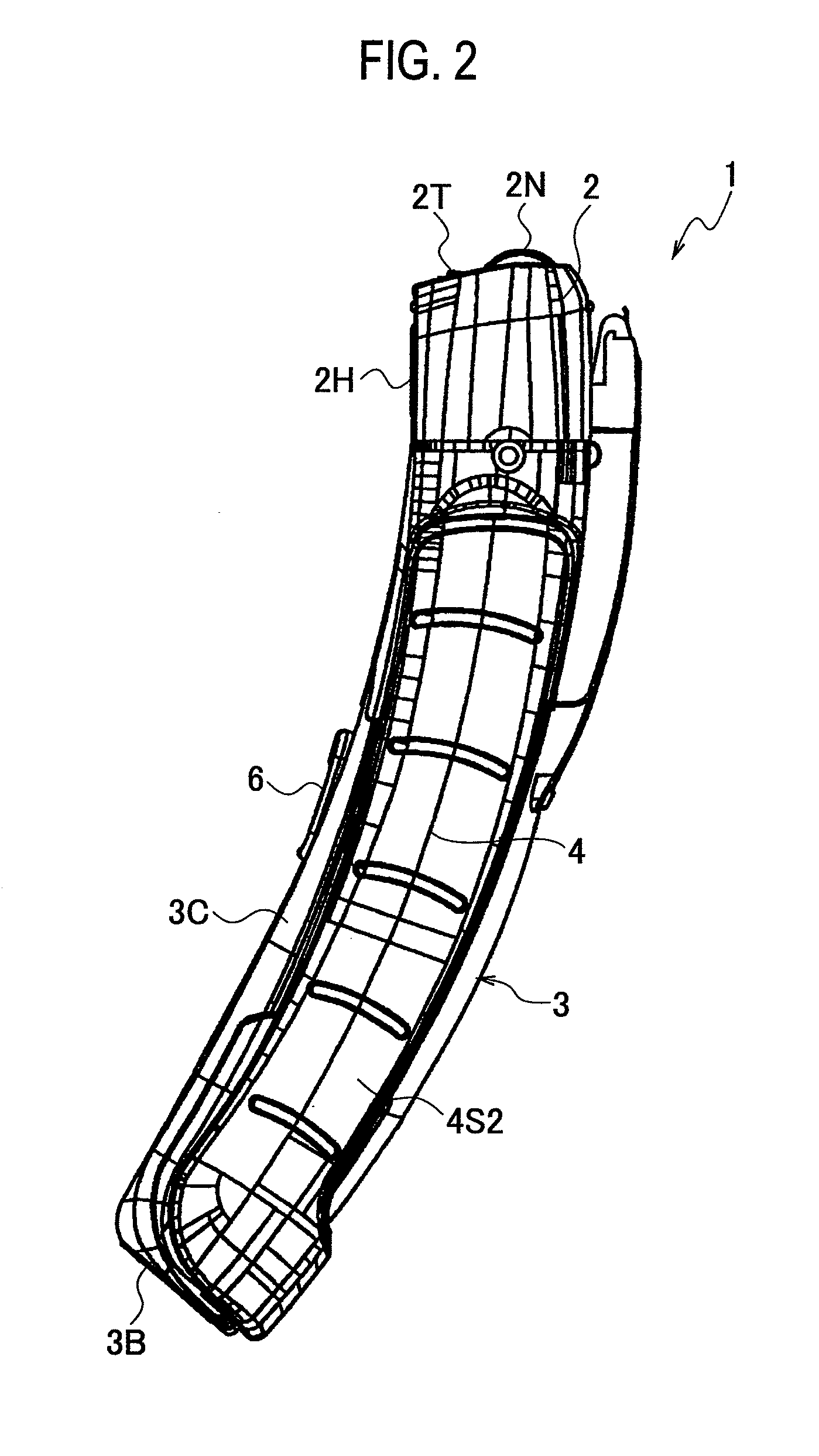
[0028]FIG. 1 to FIG. 15 show an electric hair remover, according to an embodiment of the present invention.

[0029]FIG. 1 is a front view of the electric hair remover.

[0030]FIG. 2 is a side view of...


PUM


Abstract

An electric hair remover, includes: a body part having a head end part in a longitudinal direction, a blade part for cutting hair being formed at the head end part; a holder part mounted to the body part in such a configuration as to slide along the longitudinal direction of the body part and to rotate.

Description

BACKGROUND OF THE INVENTION[0001]1. Field of the Invention[0002]The present invention relates to an electric hair remover (epilator) for removing hair.[0003]2. Description of the Related Art[0004]Conventionally, an electric hair remover such as electric razor has such a structure that a blade block for cutting hair is disposed at a head end of a body part which also serves as a holder part. A motor for driving the blade, a driver for transmitting the driving force of the motor and a battery block for driving the motor, and the like are received in the body part. Turning on (on-operation) a switch drives the motor, thereby moving the blade for removing hair.[0005]On the other hand, Japanese Patent Application Laid-Open No. 2007-105077 (=JP2007105077) discloses a manual safety razor (referred to as “T-shaped trimmer for shaving eyebrows”) which has such a structure that a body part is made bendable or telescopic. As such, the razor has a convenient configuration during operation by th...

Claims


Application Information

Patent Timeline
Patent Type & Authority Patents(United States)
IPC IPC(8): B26B19/02
CPCB26B19/382B26B19/3853
Inventor OUCHI, KAZUYUKIOGAWA, HITOSHIWANG, WEI
Owner MATSUSHITA ELECTRIC WORKS LTD
Learn More