Mid turbine frame for gas turbine engine
a gas turbine engine and frame technology, applied in the direction of engines, motors, jet propulsion plants, etc., can solve the problem of further damage to the engin
- Summary
- Abstract
- Description
- Claims
- Application Information
AI Technical Summary
Benefits of technology
Problems solved by technology
Method used
Image
Examples
Embodiment Construction
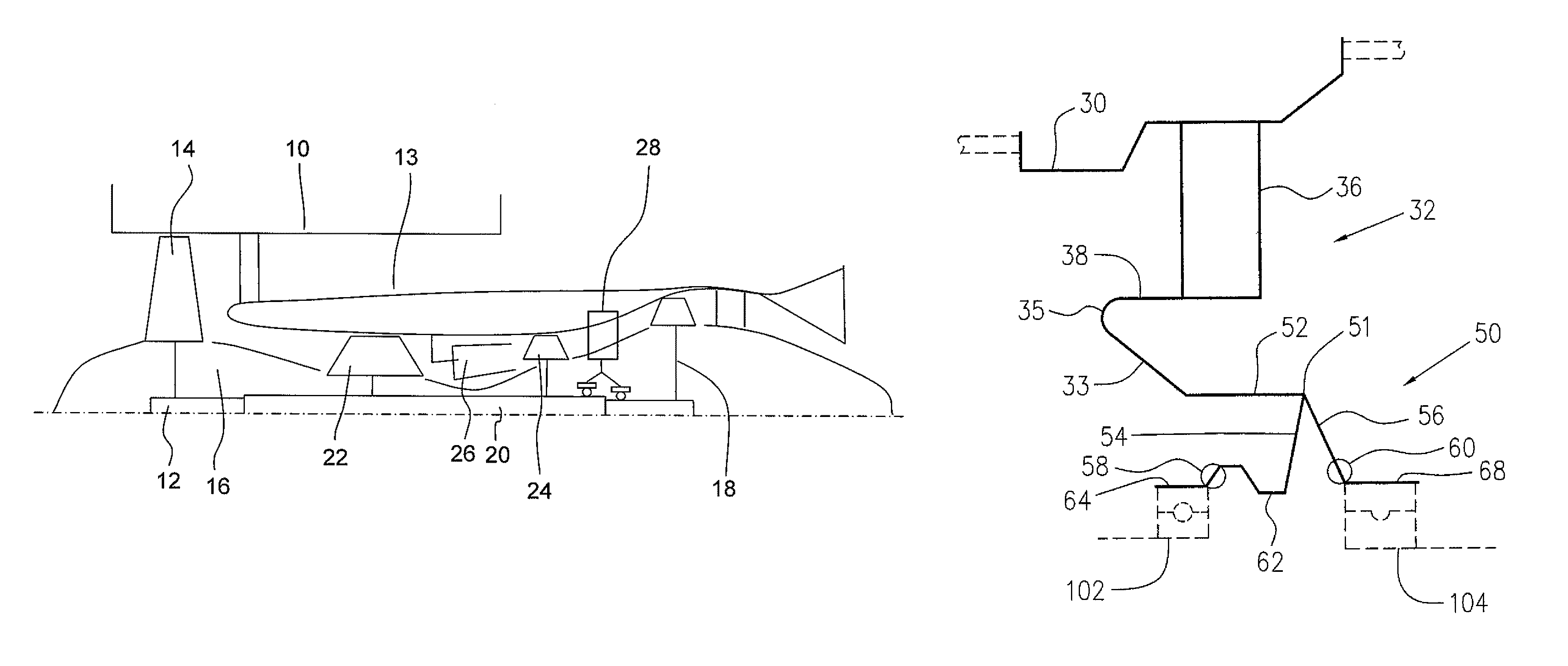
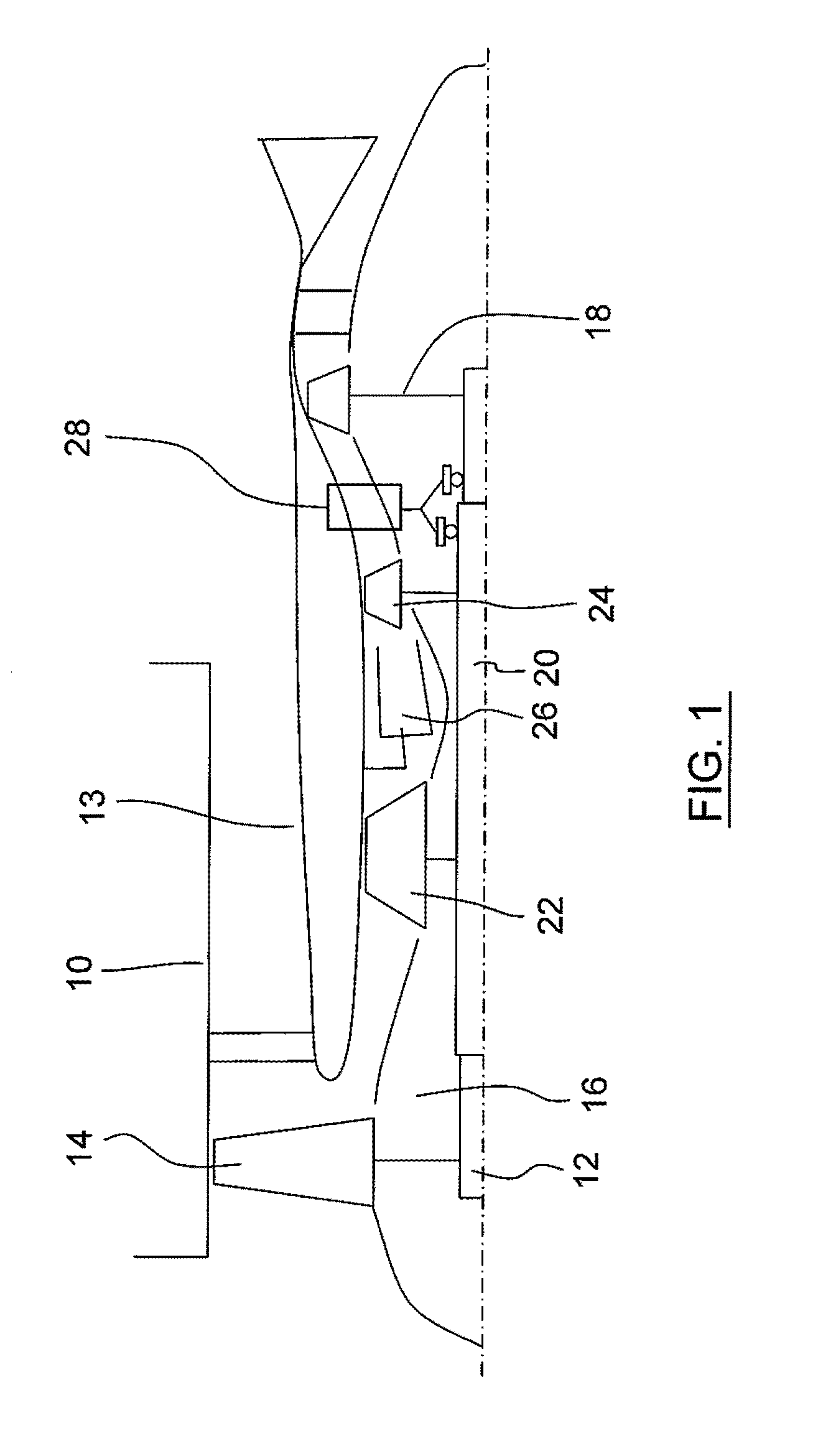
[0032]Referring to FIG. 1, a bypass gas turbine engine includes a fan case 10, a core case 13, a low pressure spool assembly which includes a fan assembly 14, a low pressure compressor assembly 16 and a low pressure turbine assembly 18 connected by a shaft 12, and a high pressure spool assembly which includes a high pressure compressor assembly 22 and a high pressure turbine assembly 24 connected by a turbine shaft 20. The core case 13 surrounds the low and high pressure spool assemblies to define a main fluid path therethrough. In the main fluid path there is provided a combustor 26 to generate combustion gases to power the high pressure turbine assembly 24 and the low pressure turbine assembly 18. A mid turbine frame system 28 is disposed between the high pressure turbine assembly 24 and the low pressure turbine assembly 18 and supports bearings 102 and 104 around the respective shafts 20 and 12.
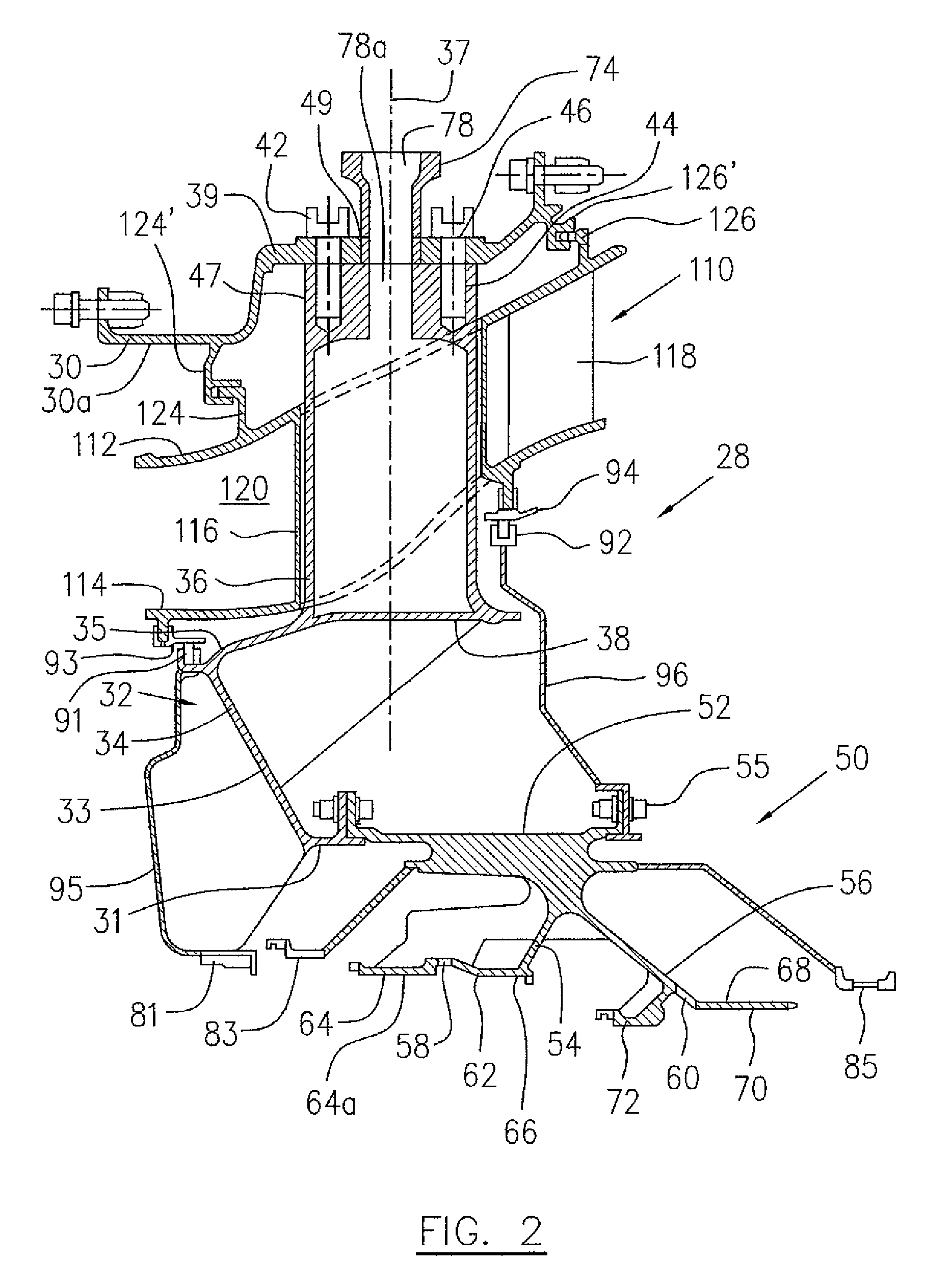
[0033]Referring to FIGS. 1-S, the mid turbine frame system 28 includes an annular oute...
PUM
 Abstract
Description
Claims
Application Information
 - R&D
- Intellectual Property
- Life Sciences
- Materials
- Tech Scout
- Unparalleled Data Quality
- Higher Quality Content
- 60% Fewer Hallucinations
Browse by: Latest US Patents, China's latest patents, Technical Efficacy Thesaurus, Application Domain, Technology Topic, Popular Technical Reports.
© 2025 PatSnap. All rights reserved.Legal|Privacy policy|Modern Slavery Act Transparency Statement|Sitemap|About US| Contact US: help@patsnap.com


