Method and apparatus of fuelling an internal combustion engine with hydrogen and methane

a technology of internal combustion engine and fuel, which is applied in the direction of mechanical equipment, machines/engines, gaseous fuels, etc., can solve the problems of lbsi engines, affecting engine performance and efficiency, and reducing performance and energy efficiency, so as to reduce compression ratio, avoid engine knocking, and improve performance and efficiency

Active Publication Date: 2012-01-10
THE UNIV OF BRITISH COLUMBIA +1
View PDF11 Cites 48 Cited by
  • Summary
  • Abstract
  • Description
  • Claims
  • Application Information

AI Technical Summary

Problems solved by technology

To avoid engine knock caused by the premature detonation of the fuel inside the combustion chamber, such engines typically operate with a compression ratio no greater than about 12:1, which is lower compared to diesel-cycle engines which have compression ratios of at least 14:1, and this affects engine performance and efficiency.
Consequently, while the exhaust gases from the combustion chambers of LBSI engines can have lower emissions of NOx, and PM compared to an equivalently sized diesel engine, such LBSI engines also have lower performance and energy efficiency, which means that to do the same amount of work, more fuel is consumed on an energy basis, and to match the full range of power and performance of a diesel engine, a larger LBSI engine is needed.
Such contradictory results show that while a considerable amount of research has been done to investigate the effects of blending natural gas and hydrogen for use in homogeneous charge spark-ignition engines, the combustion process is complex, that the effect of combusting such fuel mixtures in an engine can be very dependent upon the engine operating conditions, and that the effect of adding hydrogen and the magnitude or such effects, if any, are not obvious or easy to predict.
Furthermore, all of the published papers referenced herein relate to homogeneous charge spark-ignition engines, and while some laboratory experiments have been reported, such as shock-tube studies and non-premixed counterflow methane / heated air jet experiments, the inventors are not aware of any publications relating to experiments involving fuelling a direct injection internal combustion engine with a blended fuel mixture comprising methane and hydrogen.
Engines that are capable of injecting a gaseous fuel directly into the combustion chamber of a high compression internal combustion engine are being developed, but are not yet commercially available.
PM emissions, among other detrimental health effects, have been linked to increased cardiovascular mortality rates and impaired lung development in children.
However, with direct injection engines that are fuelled with natural gas, it has been found that there is a trade-off between NOx emissions and emissions of unburned hydrocarbons and PM.
That is, later timing for injecting the natural gas is beneficial for reducing NOx but results in higher emissions of unburned hydrocarbons and PM.
As a result, because it is necessary to reduce the emissions of each one of NOx, PM and unburned hydrocarbons, for a direct injection engine fuelled with natural gas, the higher PM emissions associated with later combustion timing effectively limits how much the timing for fuel injection can be retarded.

Method used


Image

  • Method and apparatus of fuelling an internal combustion engine with hydrogen and methane
  • Method and apparatus of fuelling an internal combustion engine with hydrogen and methane
  • Method and apparatus of fuelling an internal combustion engine with hydrogen and methane

Examples


Embodiment Construction

)

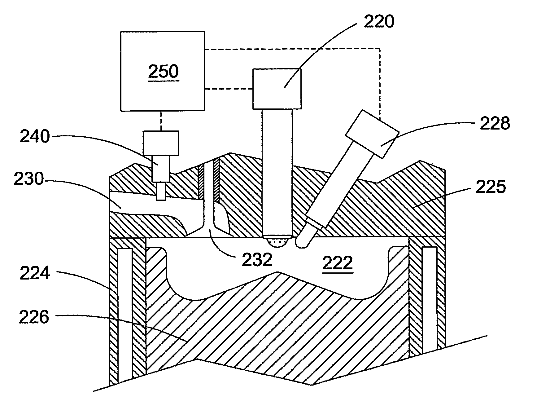
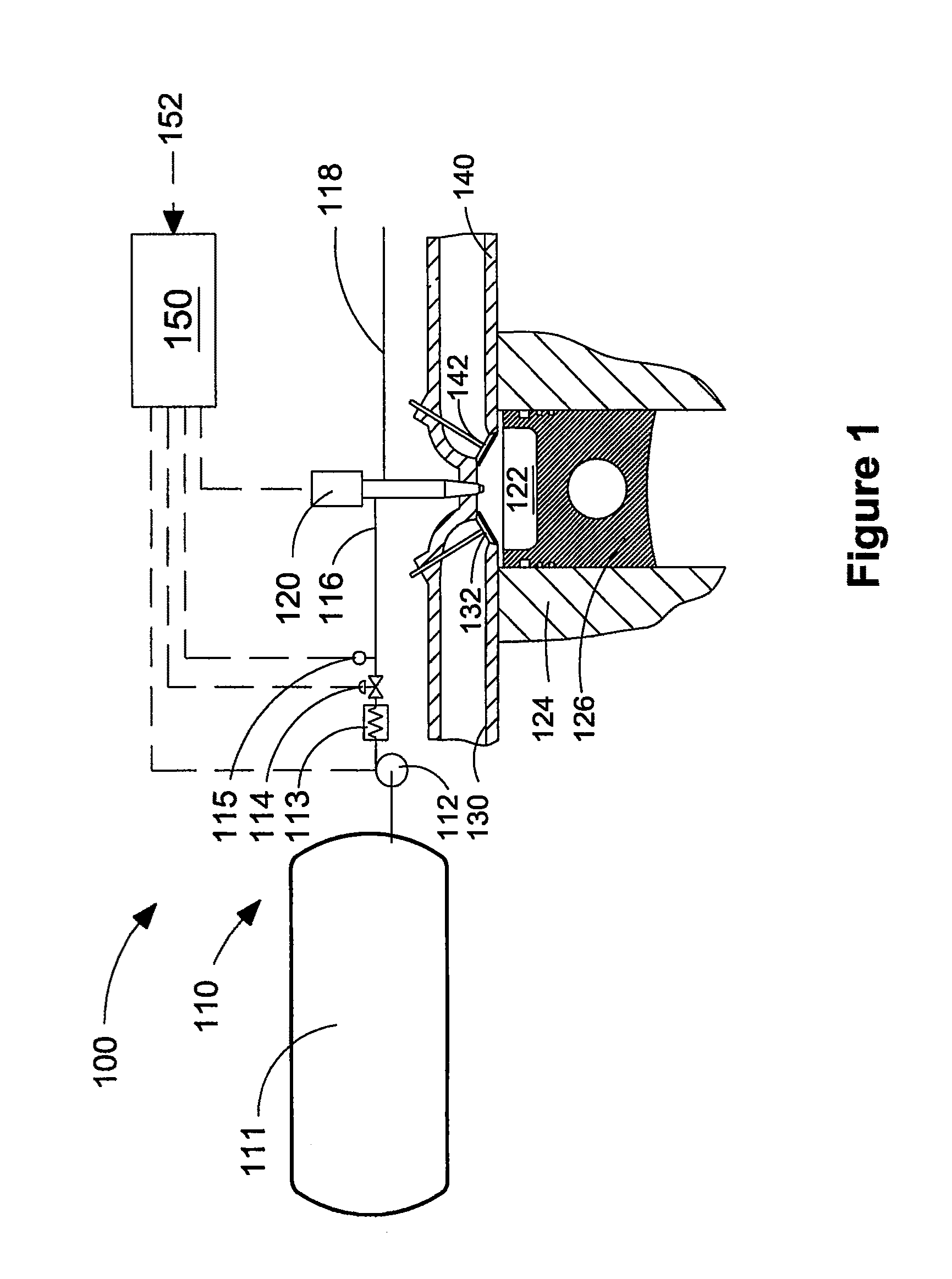
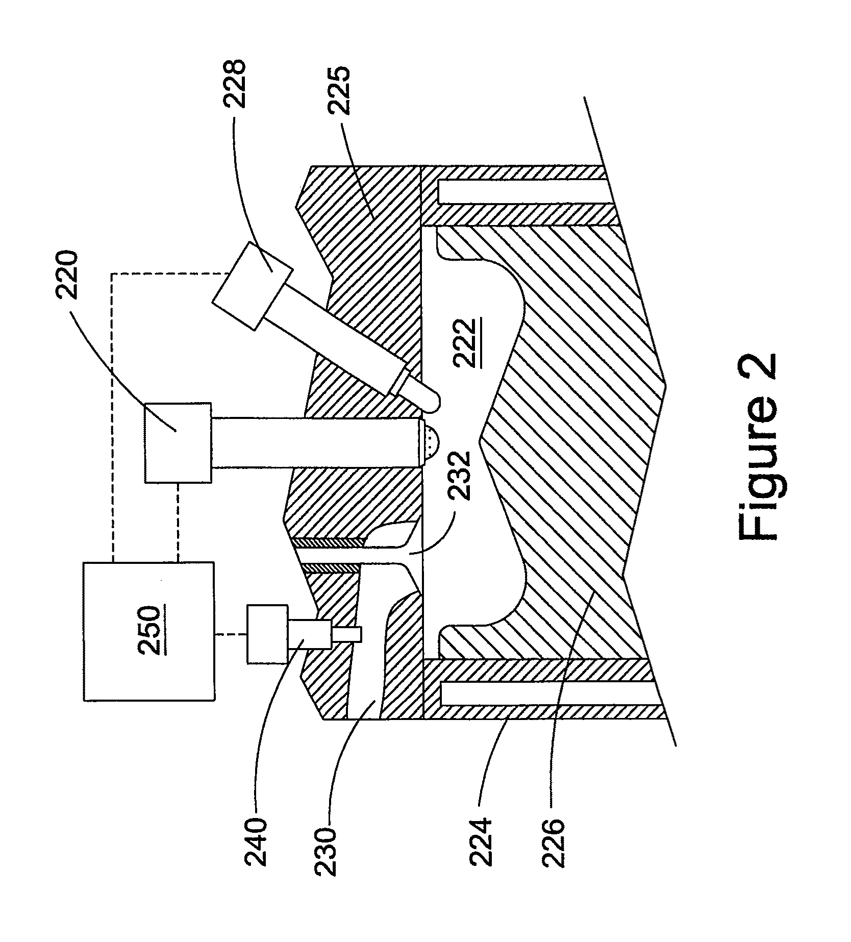
[0035]FIG. 1 is a schematic drawing of engine apparatus 100, which is adapted to be fuelled with a gaseous fuel mixture comprising methane and hydrogen. Fuel storage system 110 comprises storage vessel 111, which is made to store the compressed gaseous fuel mixture. In the illustrated embodiment, the pre-mixed gaseous fuel mixture can be stored in storage vessel 111, which is rated to store the compressed gaseous fuel mixture at a predetermined storage pressure. Storage vessel 111 is designed to comply with local regulations which can specify safety factors for ensuring containment of the gaseous fuel mixture even in the event of impact, for example if storage vessel 111 is a vehicular fuel tank that could be involved in a vehicle collision. In addition to safety factors and design strength requirements, local regulations typically impose a maximum storage pressure. Compressor 112 is operable to deliver the gaseous fuel mixture from storage vessel 111 to fuel injection valve 120, v...


PUM


Abstract

A gaseous-fuelled internal combustion engine and a method of engine operation improve combustion stability and reducing emissions of NOx, PM, and unburned hydrocarbons. The method comprises fuelling an internal combustion engine with hydrogen and natural gas, which can be directly injected into the combustion chamber together or introduced separately. Of the total gaseous fuel delivered to the engine, at least 5% by volume at standard temperature and pressure is hydrogen. For at least one engine operating condition, the ratio of fuel rail pressure to peak in-cylinder pressure is at least 1.5:1. A fuel injection valve introduces the gaseous fuel mixture directly into the combustion chamber. Two separate fuel injection valves could also introduce the methane and hydrogen separately. An electronic controller controls timing for operating the fuel injection valve(s). The engine has a preferred compression ratio of at least 14:1.

Description

CROSS-REFERENCE TO RELATED APPLICATION(S)[0001]This application is a continuation of International Application No. PCT / CA2007 / 000431, having an international filing date of Mar. 13, 2007, entitled “Method And Apparatus Of Fuelling An Internal Combustion Engine With Hydrogen And Methane”. The '431 international application claimed priority benefits, in turn, from Canadian Patent Application No. 2,539,711 filed Mar. 31, 2006. The '431 international application is hereby incorporated by reference herein in its entirety.FIELD OF THE INVENTION[0002]The present invention relates to a method and apparatus of fuelling a diesel-cycle internal combustion engine with hydrogen and methane to improve combustion stability and reduce emissions of nitrogen oxides (NOx), unburned hydrocarbons and particulate matter (PM).BACKGROUND OF THE INVENTION[0003]Because gaseous fuels such as natural gas, propane, hydrogen, and blends thereof are cleaner burning fuels compared to liquid fuels such as diesel, r...

Claims


Application Information

Patent Timeline
Patent Type & Authority Patents(United States)
IPC IPC(8): F02B13/00F02M21/02
CPCC10L3/06F02D19/024F02D19/0605F02D19/10F02M21/0215F02M21/0224F02M25/10F02M43/04F02D19/0644F02D19/0689F02D19/081F02D19/022F02B23/0657F02B23/0696F02B29/0468F02B37/00F02B43/10F02B69/04F02B2275/14F02B2275/16F02M25/0727F02M2200/46Y02T10/121Y02T10/36Y02T10/123Y02T10/32F02B3/06F02M26/23Y02T10/12Y02T10/30F02D19/08F02M21/02F02M25/00
Inventor MUNSHI, SANDEEPMCTAGGART-COWAN, GORDON P.ROGAK, STEVEN N.BUSHE, WILLIAM KENDAL
Owner THE UNIV OF BRITISH COLUMBIA
Why Eureka
Try Eureka