Multi-channel flat-tube heat exchanger

a heat exchanger and multi-channel technology, applied in indirect heat exchangers, lighting and heating apparatuses, refrigeration components, etc., can solve the problems of significant reduction of heat exchanger efficiency, two-phase maldistribution problems, adversely affecting heat exchanger efficiency, etc., and achieve the effect of reducing the maldistribution of fluid flow

Inactive Publication Date: 2012-01-10
CARRIER CORP
View PDF53 Cites 10 Cited by
  • Summary
  • Abstract
  • Description
  • Claims
  • Application Information

AI Technical Summary

Benefits of technology

[0009]It is a general object of the invention to reduce maldistribution of fluid flow in a heat exchanger having a plurality of multi-channel tubes extending between a first header and a second header.

Problems solved by technology

Non-uniform distribution, also referred to as maldistibution, of two-phase refrigerant flow is a common problem in parallel tube heat exchangers which adversely impacts heat exchanger efficiency.
Two-phase maldistribution problems are caused by the difference in density of the vapor phase refrigerant and the liquid phase refrigerant present in the inlet header due to the expansion of the refrigerant as it traversed the upstream expansion device.
Obtaining uniform refrigerant flow distribution amongst the relatively large number of small cross-sectional flow area refrigerant paths is even more difficult than it is in conventional round tube heat exchangers and can significantly reduce heat exchanger efficiency.

Method used


Image

  • Multi-channel flat-tube heat exchanger
  • Multi-channel flat-tube heat exchanger
  • Multi-channel flat-tube heat exchanger

Examples


Embodiment Construction

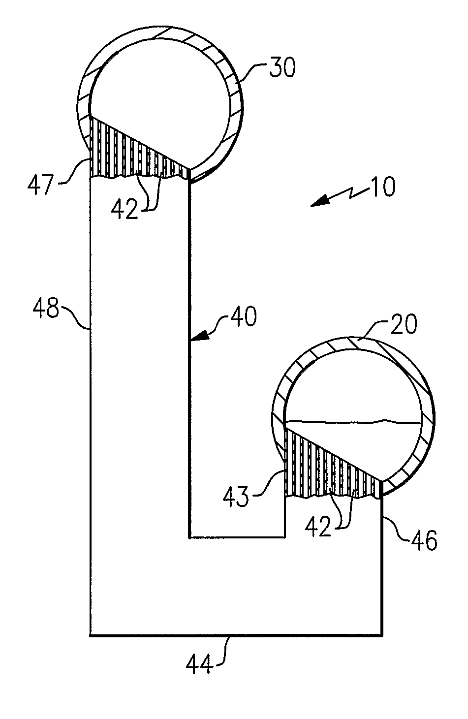
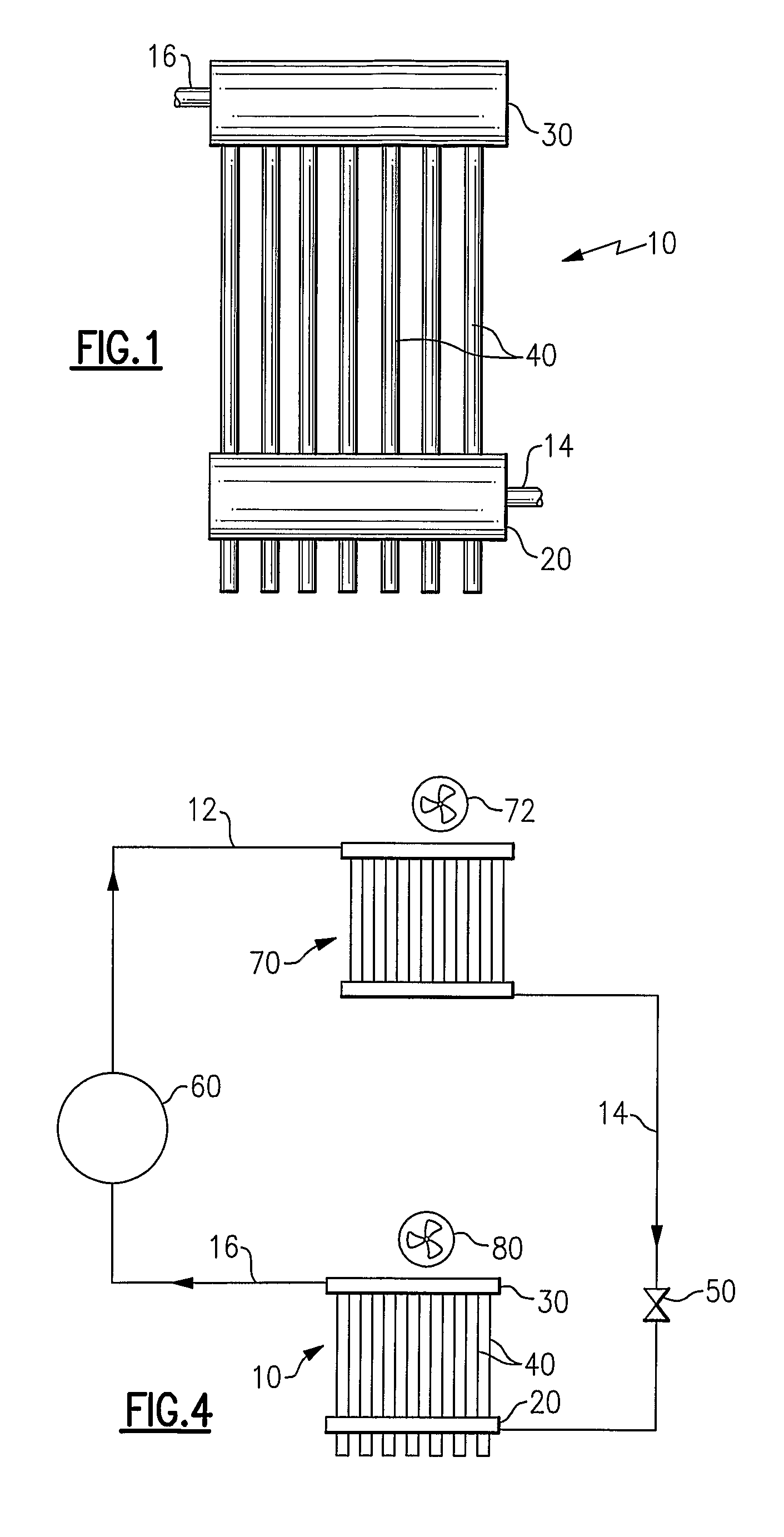
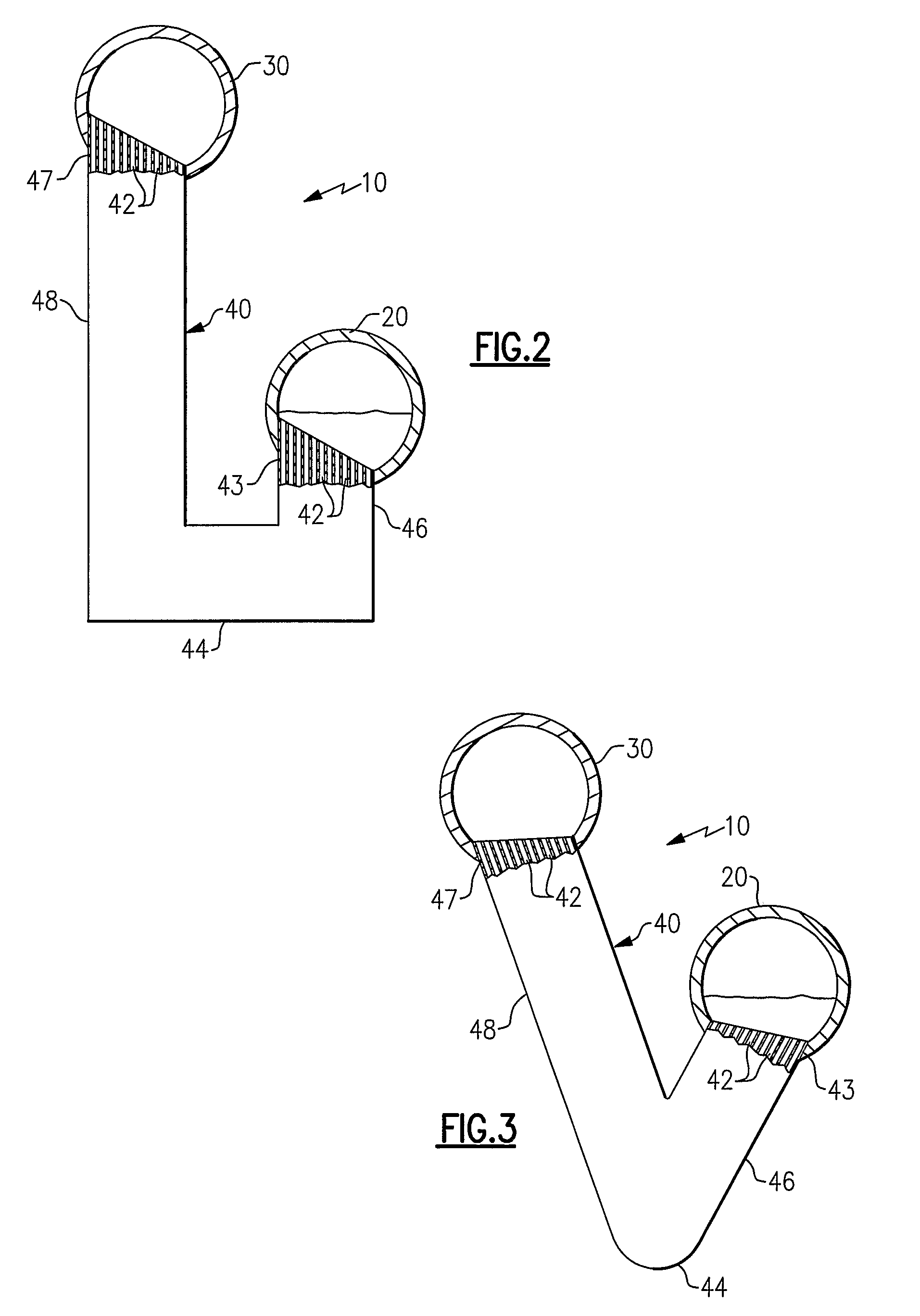
[0017]The heat exchanger 10 includes an inlet header 20, an outlet header 30, and a plurality of longitudinally generally J-shaped, multi-channel heat exchanger tubes 40 providing a plurality of fluid flow paths between the inlet header 20 and the outlet header 30. In the depicted embodiment, the inlet header 20 and the outlet header 30 comprise longitudinally elongated, hollow, closed end cylinders defining there within a fluid chamber having a circular cross-section. However, neither the inlet header 20 nor the outlet header 30 is limited to the depicted configuration. For example, the headers might comprise a longitudinally elongated, hollow, closed end cylinder having an elliptical cross-section or a longitudinally elongated, hollow, closed end body having a square, rectangular, hexagonal, octagonal, or other polygonal cross-section.

[0018]Each heat exchange tube 40 has a plurality of parallel flow channels 42 extending longitudinally, i.e. along the axis of the tube, the length ...


PUM


Abstract

A heat exchanger includes a plurality of flattened, multi-channel heat exchange tubes of generally J-shape extending between an inlet header and an outlet header. Each heat exchange tube has a base bend that extends horizontally between the vertically extending relatively shorter leg, which is in fluid flow communication with the fluid chamber of the inlet header, and the vertically extending relatively longer leg, which is in fluid flow communication with the fluid chamber of the outlet header.

Description

CROSS-REFERENCE TO RELATED APPLICATION[0001]Reference is made to and this application claims priority from and the benefit of U.S. Provisional Application Ser. No. 60 / 649,433, filed Feb. 2, 2005, and entitled J-SHAPE MINI-CHANNEL HEAT EXCHANGER, which application is incorporated herein in its entirety by reference.FIELD OF THE INVENTION[0002]This invention relates generally to heat exchangers having a plurality of parallel tubes extending between a pair of headers, also sometimes referred to as a manifolds, and, more particularly, to providing fluid expansion within the an header of a heat exchanger for improving distribution of fluid flow through the parallel tubes of the heat exchanger, for example a heat exchanger in a refrigerant vapor compression system.BACKGROUND OF THE INVENTION[0003]Refrigerant vapor compression systems are well known in the art. Air conditioners and heat pumps employing refrigerant vapor compression cycles are commonly used for cooling or cooling / heating ai...

Claims


Application Information

Patent Timeline
Patent Type & Authority Patents(United States)
IPC IPC(8): F28F9/02F28D7/06
CPCF25B39/02F28D1/0475F28D1/0476F25B2400/22F25B2500/01F28F9/00F28F9/013
Inventor GORBOUNOV, MIKHAIL B.VAISMAN, IGOR B.VERMA, PARMESHSYLVIA, LISA P.CHANG, XIAOYUANWINCH, GARY D.
Owner CARRIER CORP
Why Eureka
Try Eureka