Traction kite with deformable leading edge

a technology of leading edge and traction kite, which is applied in the direction of toys, marine propulsion, toy aircrafts, etc., can solve the problems of not being able to disclose or suggest a propulsive wing, and achieve the effect of facilitating selective deformation of the leading edge and the overall angle of attack, facilitating greater amount of twisting and bending, and high elasticity

Inactive Publication Date: 2012-01-17
RIDE BEST
View PDF12 Cites 6 Cited by
  • Summary
  • Abstract
  • Description
  • Claims
  • Application Information

AI Technical Summary

Benefits of technology

[0012]The present invention overcomes the disadvantages and limitation of the prior art by providing a leading edge inflatable traction kite having a compound leading edge structure that includes a plurality of spaced segments that are fabricated from a material having elastic deformation characteristics that allow for a greater amount of twisting and bending as compared with prior art designs. In a preferred embodiment, the inflatable leading edge includes a series of elastically deformable segments that are inter-disposed at locations throughout the length of the leading edge to facilitate selective deformation of the leading edge and overall angle of attack. The elastically deformable segments are preferably integrally formed as part of the leading edge support and are comprised of a material with a high elasticity, namely a higher elasticity or stretch factor than the remaining leading edge segments or remainder of the leading edge depending on the number of elastically deformable segments included in the overall leading edge. Providing elastically deformable segments, e.g. segments of high elasticity, dispersed along the leading edge combined with segments of lower elasticity maximizes responsiveness and control by allowing leading edge deformation in response to user applied force, while the providing sufficient support to maintain kite stability.
[0013]Accordingly, it is an object of the present invention to provide a leading edge inflatable traction kite having improved performance characteristics.
[0014]Another object of the present invention is to provide a leading edge inflatable traction kite that provides sufficient support to maintain stability while maximizing the amount of deformation for a given applied force.
[0015]Still another object of the present invention is to provide a leading edge traction kite, wherein the leading edge is comprised of a series of deformable and twistable segments inter disposed within more rigid support segments to increase kite deformation and wing warping.
[0016]It is yet another object of the present invention to provide a leading edge traction kite that provides optimum performance characteristics, in particular the ability to perform quick turns and maneuvers.
[0017]It is furthermore another object of the present invention to provide a leading edge inflatable traction kite that is inexpensive to manufacture, therefore allowing for widespread distribution.

Problems solved by technology

The prior art, however, fails to disclose or suggest a propulsive wing that maximizes control responsiveness by providing an inflatable leading edge that is capable increased elastic deformation while maintaining sufficient structural rigidity to maintain stability in flight.

Method used


Image

  • Traction kite with deformable leading edge
  • Traction kite with deformable leading edge
  • Traction kite with deformable leading edge

Examples


Embodiment Construction

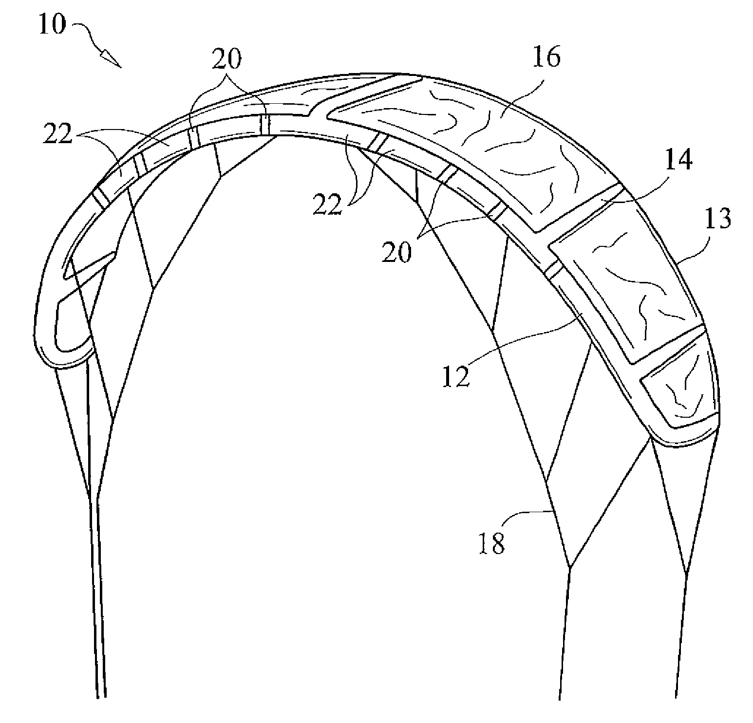
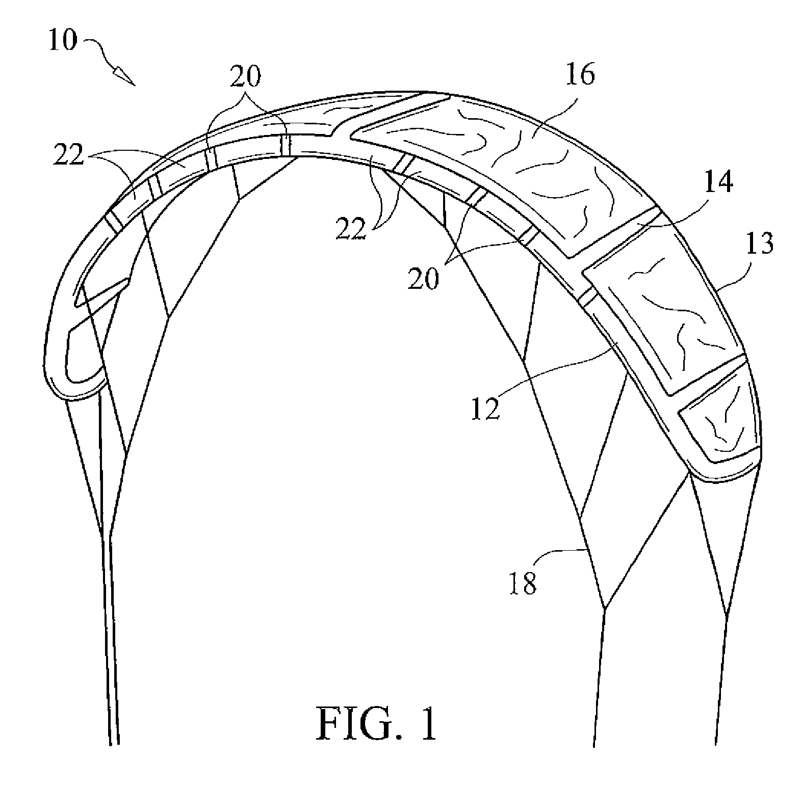
[0029]With reference now to the drawings, FIG. 1 shows a perspective view of a traction kite having an inflatable leading edge in accordance with the present invention. Kite 10 includes an inflatable, elastically deformable leading edge spar 12 extending across the entire longitudinal front side of kite 10. Leading edge spar 12 comprises an inflatable tubular structure as more fully detailed herein. A series of inflatable struts or ribs 14 extend generally perpendicularly out from the inflatable leading edge 12 towards the trailing edge 13 of the kite 10. Inflatable ribs 14 are preferably in fluid communication with leading edge 12 such that inflation of leading edge 12 causes inflation of ribs 14. Leading edge 12 and ribs 14 form the support structure for the canopy 16 of kite 10. Canopy 16 is connected to and extends between parallel ribs 14 and the leading edge strut 12 as is generally known in the art. Leading edge 12 and canopy 16 serve as the main surfaces over which air flows...


PUM


Abstract

A leading edge inflatable traction kite wherein the leading edge structure includes a plurality of spaced segments that are fabricated from a material with a higher elasticity, thus allowing for a greater amount of twisting and bending. The inflatable leading edge includes a series of elastically deformable segments disposed throughout the length thereof to facilitate selective torsional deformation of the leading edge and resulting overall angle of attack of the kite. These elastically deformable segments are preferably integrally formed as part of the leading edge support and are comprised of a material with a high elasticity, namely a higher elasticity than the remaining leading edge segments. Providing elastically deformable segments of high elasticity dispersed along the leading edge combined with regions of lower elasticity maximizes responsiveness and control by allowing leading edge deformation in response to user applied force, while the providing sufficient support to maintain kite stability.

Description

CROSS REFERENCE TO RELATED APPLICATIONS[0001]This application claims the benefit of provisional U.S. Patent Application Ser. No. 61 / 051,033, filed on May 7, 2008.STATEMENT REGARDING FEDERALLY SPONSORED RESEARCH OR DEVELOPMENT[0002]N / ACOPYRIGHT NOTICE[0003]A portion of the disclosure of this patent document contains material that is subject to copyright protection. The copyright owner has no objection to the facsimile reproduction by anyone of the patent document or patent disclosure as it appears in the Patent and Trademark Office patent file or records, but otherwise reserves all copyrights rights whatsoever.BACKGROUND OF THE INVENTION[0004]1. Field of the Invention[0005]The present invention relates to propulsive wings and traction kites, used for applying a traction force and / or pulling a load. More particularly the present invention relates to traction kite having a generally tubular inflatable leading edge comprised of multiple segments, with certain segments comprised of defor...

Claims


Application Information

Patent Timeline
Patent Type & Authority Patents(United States)
IPC IPC(8): A63H27/08
CPCB63B35/7976B63H8/14
Inventor SHOGREN, ALEXANDERSTIEWE, PETER
Owner RIDE BEST
Why Eureka
Try Eureka