
Flexible display device

a display device and flexible technology, applied in the field of display devices, to achieve the effect of improving the reliability of us

Active Publication Date: 2012-01-17
E INK HLDG INC
View PDF5 Cites 64 Cited by
  • Summary
  • Abstract
  • Description
  • Claims
  • Application Information

AI Technical Summary

Benefits of technology

[0008]The invention is directed to a flexible display device with improved use reliability.
[0011]For the flexible display device of the invention, since there are a plurality of curving-restricting structures disposed on the display panel, the adjacent curving-restricting structures can resist against with each other for restricting the bending angle of the display panel when the flexible display device is bent to a predetermined extent. Therefore, the internal elements of the display panel may avoid damages resulting from the display panel being over-bent, and thus the unusual displaying due to the over-bent display panel may be prevented and the use reliability of the flexible display device may be improved.

Problems solved by technology

Thus, when the flexible display device is bent to over an extent the materials can bear, the thin film transistors array would be destroyed and the flexible display device may result in unusual displaying.
Therefore, it is one of the important issues for people skilled in this art that how to avoid the unusual displaying resulting from the flexible display device under over-bending.

Method used


Image

  • Flexible display device
  • Flexible display device
  • Flexible display device

Examples


Embodiment Construction

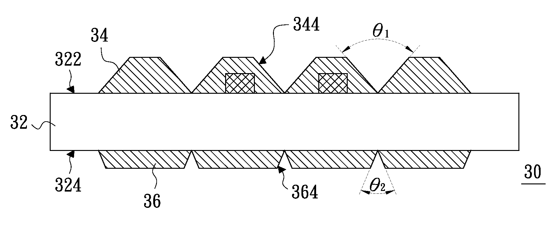
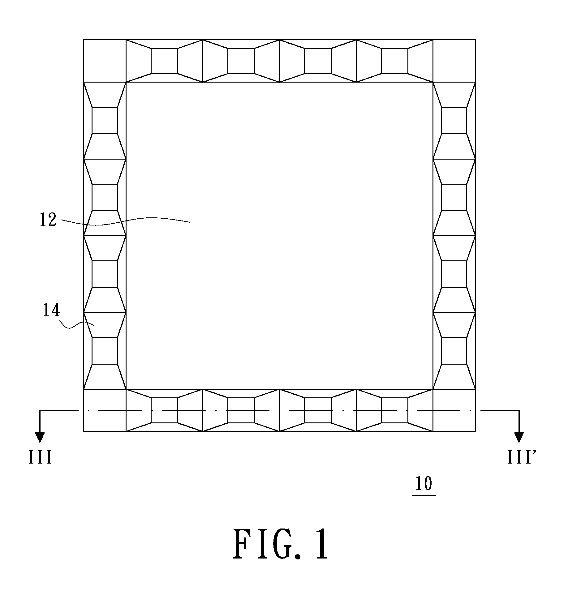
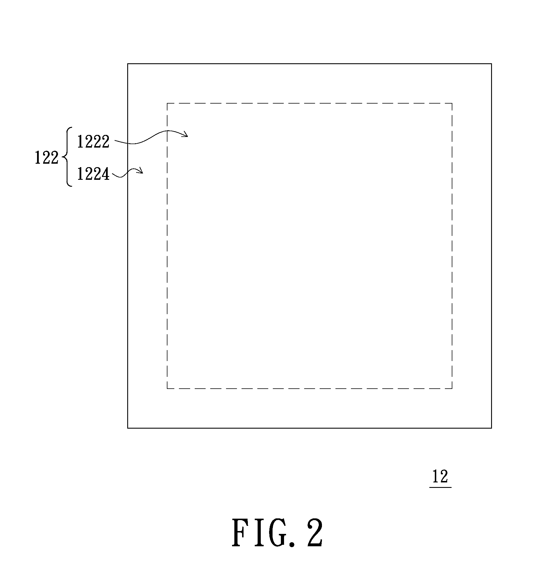
[0022]FIG. 1 is a schematic view of the flexible display device according to an embodiment of the invention. FIG. 2 is a schematic view of the display panel of the flexible display device shown in FIG. 1. FIG. 3 is a schematic cross-sectional view along line III-III′ of the flexible display device shown in FIG. 1. Referring to FIG. 1 to FIG. 3, the flexible display device 10 comprises a display panel 12 and a plurality of curving-restricting structures 14. The display panel 12 has a display surface 122 and a bottom surface 124 opposite thereto. The display surface 122 has a visible region 1222 and an outer region 1224 surrounding the visible region 1222. The curving-restricting structures 14 are disposed in the outer region 1224, and each curving-restricting structure 14 has a top surface 142 and at least a slanted side wall 144. The top surfaces 142 of adjacent curving-restricting structures 14 are separated to each other and the slanted side walls 144 thereof face to each other.

[0...


PUM


Abstract

A flexible display device includes a display panel and a plurality of curving-restricting structures. The display panel has a display surface and a bottom surface opposite thereto. The display surface has a visible region and an outer region surrounding the visible region. The curving-restricting structures may be disposed on at least one of the outer region of the display surface and the bottom surface of the display panel. Each curving-restricting structure has a top surface and at least a slanted side wall. The top surfaces of adjacent curving-restricting structures are spaced with each other, and the slanted side walls of adjacent curving-restricting structures face each other. When the flexible display device are curved to a predetermined extent, adjacent curving-restricting structures may resist against with each other to prevent the display panel from being unduly curved to be damaged, and thus a use reliability of the flexible display device is improved.

Description

[0001]This application claims priority to a Taiwan application No. 098108836 filed Mar. 18, 2009.BACKGROUND[0002]1. Field of the Invention[0003]The invention relates to a display device, and more particular, to a flexible display device.[0004]2. Description of the Related Art[0005]With progress of science and technology, display devices are used in any electric products popularly. Moreover, since the development trend of the portable electrical product is to achieve light weight and thin thickness, the flexible display device are researched.[0006]Presently, most flexible display devices use thin film transistors (TFTs) array for controlling whether the pixels are acted or not. The thin film transistors array is generally made of several materials including the ceramic material with bad ductility. Thus, when the flexible display device is bent to over an extent the materials can bear, the thin film transistors array would be destroyed and the flexible display device may result in unu...

Claims


Application Information

Patent Timeline
Patent Type & Authority Patents(United States)
IPC IPC(8): H05K7/14
CPCG02F1/133305H05K1/0281G09F9/301H05K1/189G02F2001/133388G02F2201/54H05K3/284H05K2201/09018H05K2201/10128H05K2201/10136G02F1/133388
Inventor HSIAO, PO-WENTSAI, YUAN-CHIHSHINN, TED-HONG
Owner E INK HLDG INC
Learn More