
Squeezing device for a flat-body wiper and cleaning system

a technology of squeezing device and wiper, which is applied in the direction of carpet cleaners, cleaning equipment, cleaning machines, etc., can solve the problems of only fixing the wiping cover and placing the wiping cover very carefully

Active Publication Date: 2012-01-24
CARL FREUDENBERG KG
View PDF26 Cites 6 Cited by
  • Summary
  • Abstract
  • Description
  • Claims
  • Application Information

AI Technical Summary

Benefits of technology

[0005]An object of the present invention is to refine a squeezing device for a wiping cover of a flat-body wiper in such a way that the wiping cover is automatically brought into the optimum position for squeezing out when it is inserted into the squeezing shaft, without this requiring special handling by the user and without danger arising of tipping the container carrying the squeezing device. An additional or alternate object of the present invention is to provide a cleaning system including a flat-body wiper and a squeezing device, in which the flat-body wiper and the squeezing device are tailored to one another in such a way that wringing out may be performed easily and efficiently, but the functioning of the flat-body wiper is not impaired due to its tailoring to the squeezing device.
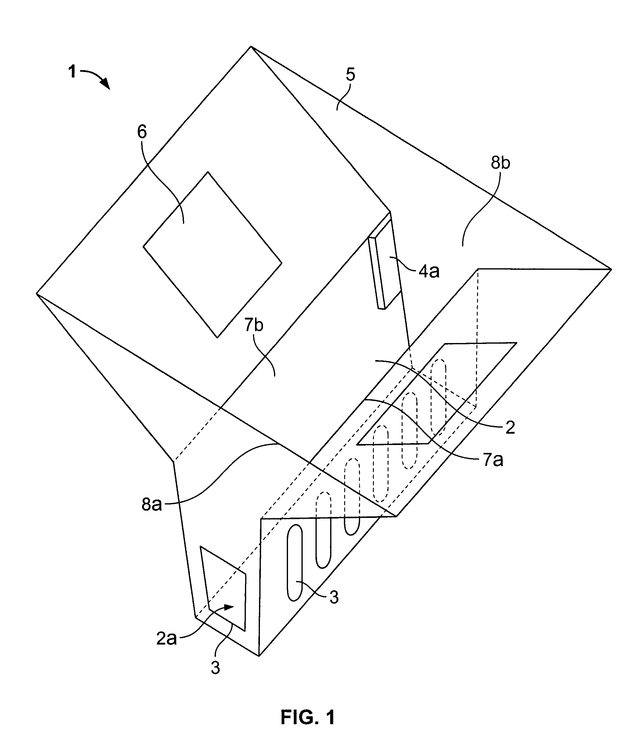
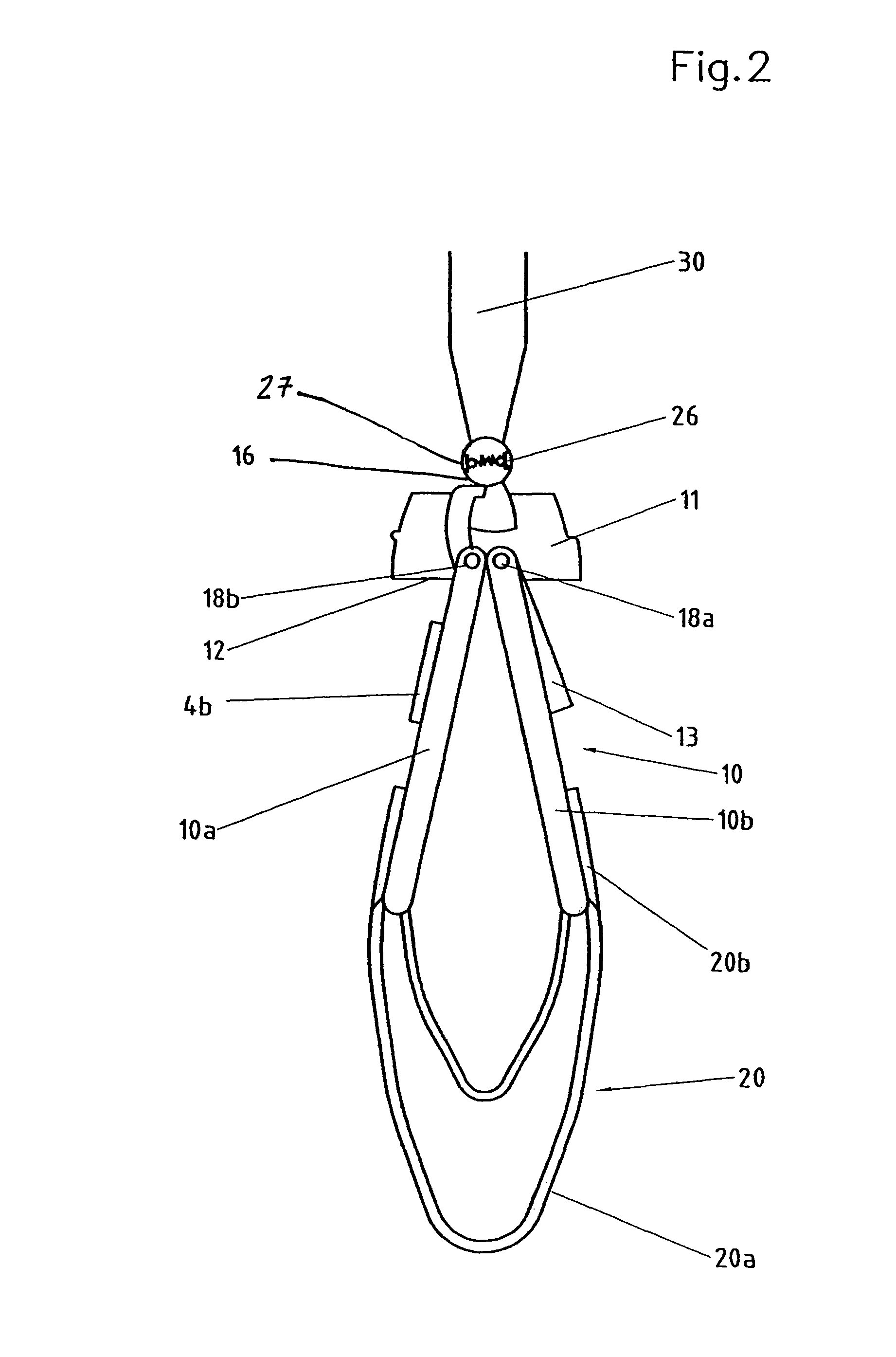
[0006]According to the present invention, in a squeezing device for a flat-body wiper, which includes an essentially funnel-shaped squeezing shaft, which tapers conically downward, having counterpressure surfaces, into which the wiping cover, in an essentially vertical position of the wiper plate, partially detached therefrom and hanging downward, may be introduced from above and squeezed out through pressure on the handle, the wiper plate also being able to be at least partially introduced into the squeezing shaft for the squeezing, so that its face pointing downward forms a pressure surface, and devices are provided for stabilizing the wiper plate against tipping during insertion and squeezing out in the squeezing shaft. Using this measure, the wiping cover and the wiper plate are automatically guided, already during insertion into the squeezing shaft of the squeezing basket, in such a way that the wiping cover is automatically brought into a favorable position for squeezing and the force exerted by the user is automatically optimally converted into pressure on the wiping cover. In particular, lateral forces on the walls of the squeezing shaft, which could cause the container supporting the squeezing device, which contains cleaning fluid, to tip, are avoided.

Problems solved by technology

The known cleaning device has the disadvantage that the wiping cover must be placed very carefully as it is inserted into the squeezing basket in order to reach the desired fold arrangement.
A further disadvantage is that, in the operating position, the wiping cover is only fixed in the forward region of the wiper plate.

Method used


Image

  • Squeezing device for a flat-body wiper and cleaning system
  • Squeezing device for a flat-body wiper and cleaning system
  • Squeezing device for a flat-body wiper and cleaning system

Examples


Embodiment Construction

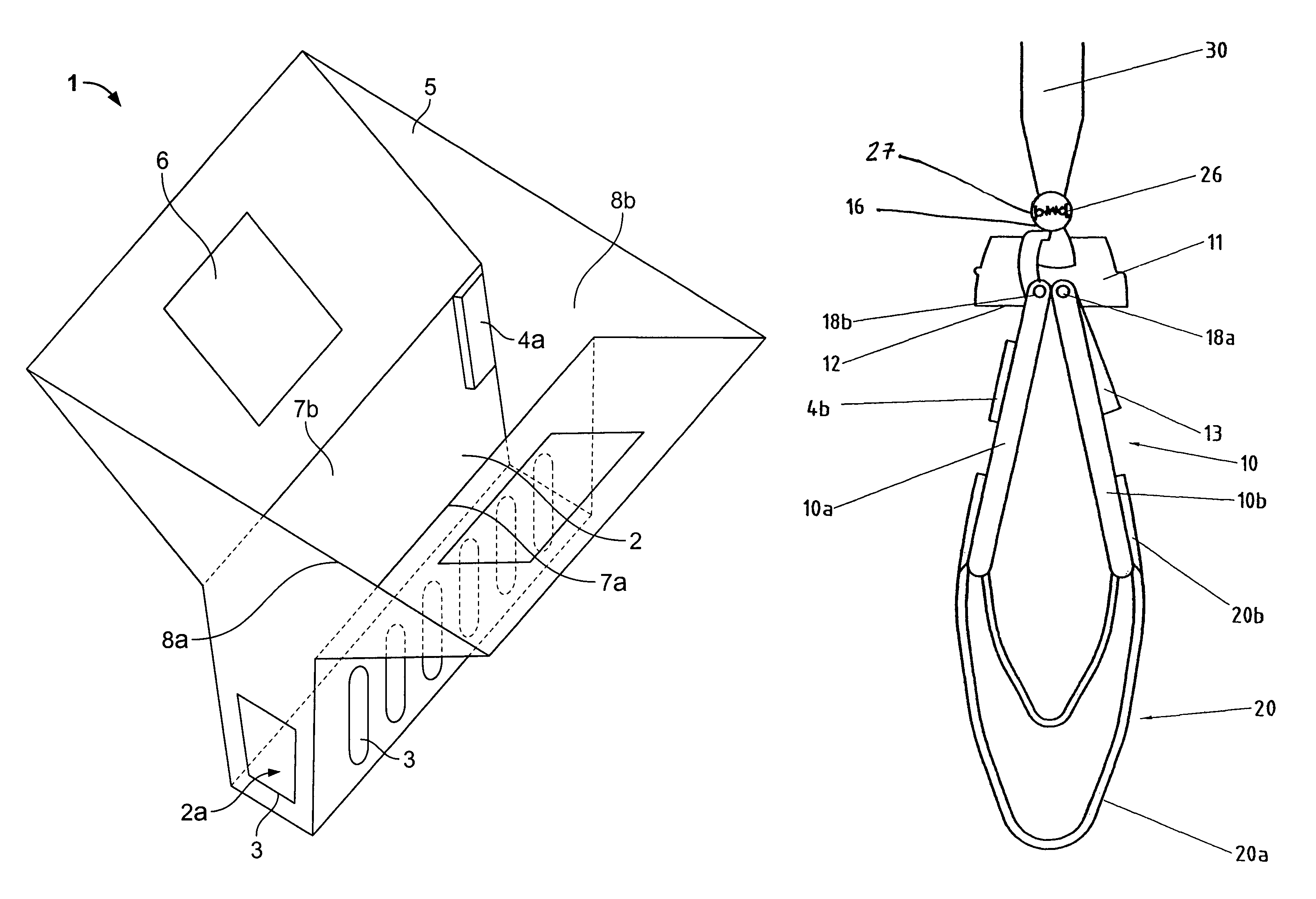
[0036]A squeezing device 1 according to the present invention, having a squeezing shaft 2 having inner walls 7a, 7b and / or 8a, 8b diametrically opposed to one another, is shown in FIG. 1. Squeezing shaft 2 has a conically downward tapering shape, which is essentially funnel-shaped, having a shaft floor (2a) with a rectangular cross section, as shown in FIG. 1. Counterpressure surfaces and drain openings 3 for draining the cleaning liquid squeezed out of the wiping cover are located in the lower region. Furthermore, guide elements 4a, on which corresponding counter-guide elements on the wiper plate are supported, may be seen in the upper region of squeezing shaft 2. An insertion funnel 5 adjoins squeezing shaft 1 from above. This funnel expands greatly conically upward and is used as an insertion aid for the wiping cover with the wiper plate. Rectangular openings6 are positioned on two diametrically opposed lateral surfaces of insertion funnel 5, into which the two ends of a middle p...


PUM

PropertyMeasurementUnit
Pressureaaaaaaaaaa
Ratioaaaaaaaaaa
Heightaaaaaaaaaa

Abstract

A squeezing device for a wiping cover of a flat-body wiper, the wiper cover hanging downward and partially detached from a wiper plate of the flat-body wiper in a vertical position of the wiper plate, the wiper plate including a downward facing pressure surface in the vertical position. The squeezing device includes a funnel-shaped squeezing shaft having a counterpressure surface in a lower region of the squeezing shaft. The squeezing shaft is configured to receive the wiper cover and at least a portion of the wiper plate in the vertical position of the wiper plate so that a squeezing pressure of the pressure surface against the counterpressure surface squeezes out the wiper cover. The squeezing shaft includes stabilizing devices configured to stabilize the wiper plate against tipping relative to a first plane from the vertical position. In addition a cleaning system including the squeezing device and a method of squeezing a wiping cover of a flat-body wiper with the squeezing device.

Description

[0001]This application claims priority to German Patent Application DE 102 105 69.3-15, filed Mar. 9, 2002, which is incorporated by reference herein.BACKGROUND[0002]The present invention relates generally to a cleaning device, and particularly to a squeezing device for a wiping cover of a flat-body wiper. Furthermore, the present invention relates to the use of such a squeezing device and a cleaning system, which includes such a squeezing device.[0003]A cleaning device having a flat-body wiper and a squeezing device for a wiping cover of a flat body wiper is known from German Patent Document DE 196 20 633 C2. The flat-body wiper has a handle and a wiper plate, which is connected to the handle via a connection element having a joint. In the forward region of the wiper plate, viewed in the wiping direction, a clamping device is positioned for attaching a wiping cover. In the rear region, the wiping cover is held by the wiper plate pressing down its fabric. To squeeze out the wiping c...

Claims


Application Information

Patent Timeline
IPC IPC(8): A47L13/58A47L13/258
CPCA47L13/258A47L13/58
Inventor DINGERT, UWEJUERGENS, RALF
Owner CARL FREUDENBERG KG
Learn More