Clip

a technology of a clip and a sleeve is applied in the field of clips, which can solve the problems of long time required for fastening the console box, the inability to absorb the position deviation in the longitudinal direction at the right angle relative to this longitudinal direction, etc., and achieve the effect of convenient operation

Active Publication Date: 2012-01-24
DAIWA KASEI IND CO LTD +1
View PDF9 Cites 1 Cited by
  • Summary
  • Abstract
  • Description
  • Claims
  • Application Information

AI Technical Summary

Benefits of technology

[0008]The present invention has been made to solve the problems described above, and an objective thereof is to provide a clip which is capable of easily absorbing the positional deviation of the attachment member relative to the attachment receiving member in a state where the clip is always integrally handled with the attachment member to which the clip is assembled, and which also enables attachment and detachment of the attachment member to and from the attachment receiving member in an extremely easy one-touch operation.
[0022]In this case, a pair of contact portions is brought into contact with the attachment receiving member, and a pair of elastic locking pieces is elastically locked with the periphery of each longer side portion of the second long hole of the attachment receiving member. As a result, the water-proof elastic member is compressed in the thickness direction and is pinched between the flat plate portion and the attachment receiving member. Thus, the second long hole can be assuredly waterproof.

Problems solved by technology

However, there still remains a problem that the positional deviation in a direction at right angle relative to this longitudinal direction cannot be absorbed.
These operations are much troublesome, and lead to a problem that much time is required for fastening the console box to the floor of the vehicle body.

Method used


Image

  • Clip
  • Clip
  • Clip

Examples


Embodiment Construction

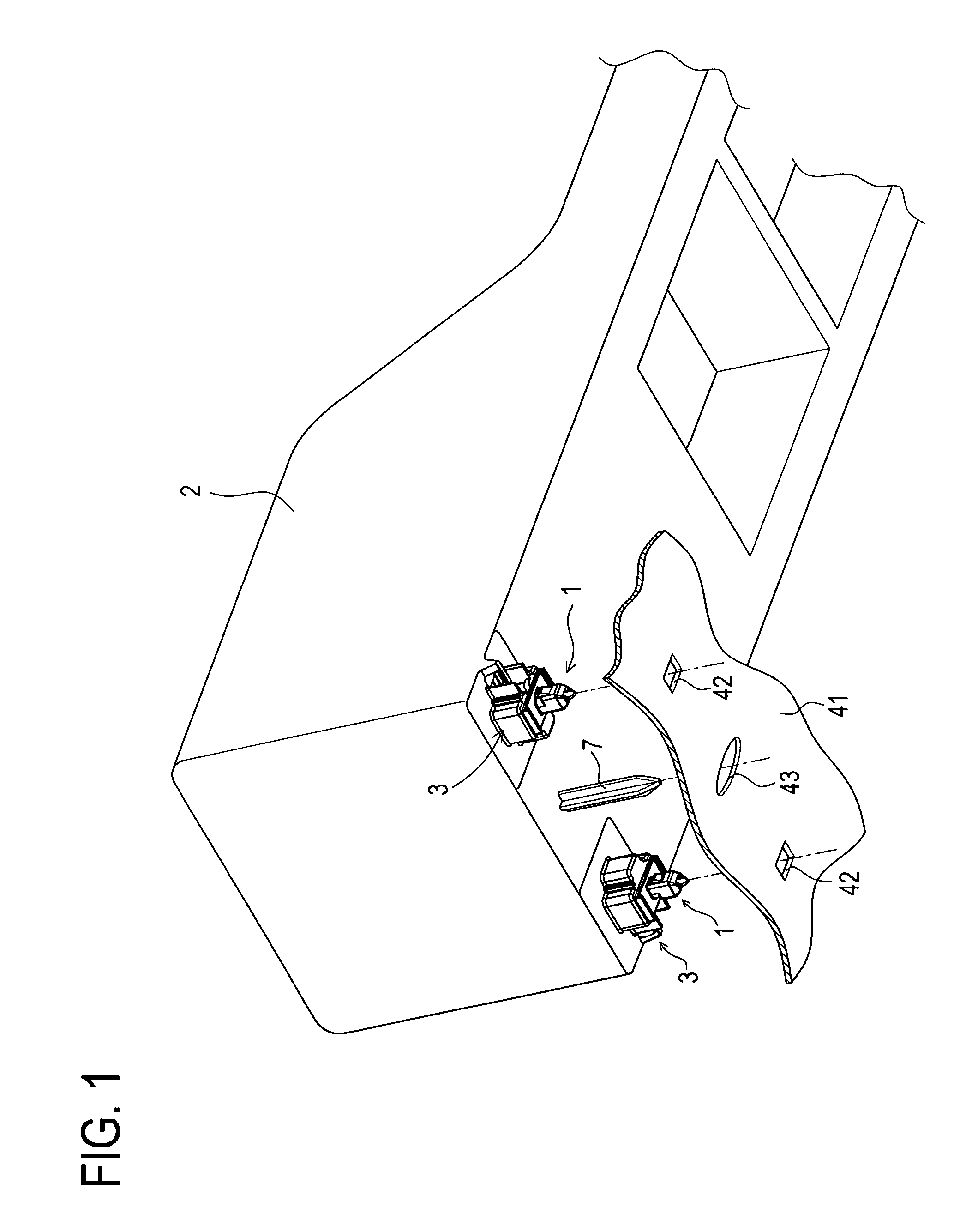
[0081]Hereinafter, a clip according to the present invention will be described in detail with reference to the drawings based on an embodiment which has embodied the present invention. First, an entire structure related to a clip according to this embodiment, an assembling portion of the console box as an attachment member to which the clip is assembled, and each long hole of the attachment receiving member composed of a metal plate (body) to constitute an automobile body with which the clip is locked is described based on FIG. 1.

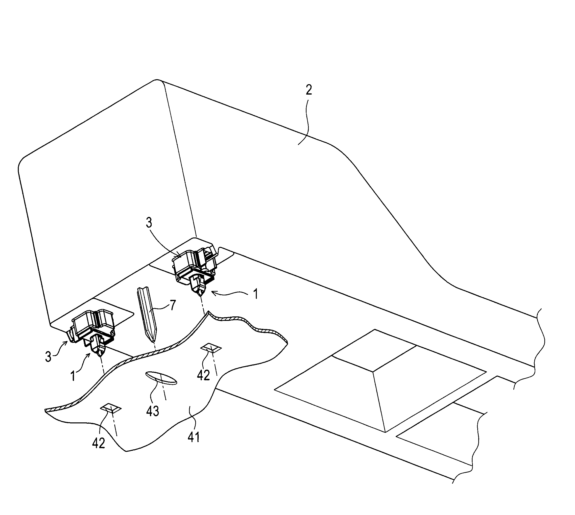
[0082]FIG. 1 is a perspective view schematically showing a clip according to this embodiment, an assembling portion of a console box to which the clip is assembled, and each long hole of the attachment receiving member with which the clip is locked.

[0083]As shown in FIG. 1, the clip 1 is assembled to each of a pair of assembling portion 3 provided on the left and right corner portions at the front side on the bottom surface portion of the console box 2. On ...


PUM


Abstract

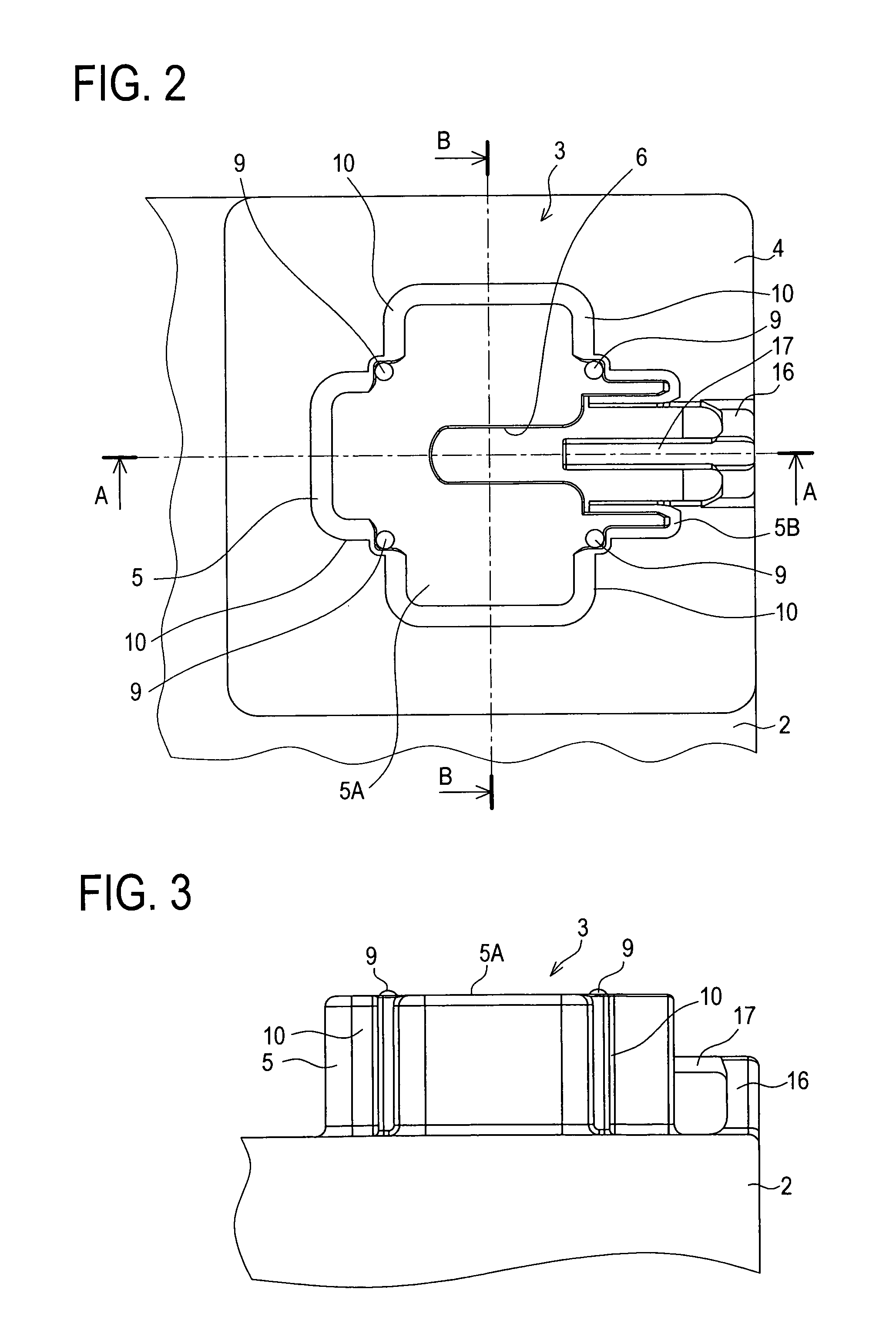
Each clip 1 is fitted into a cutaway groove portion 6 of a pedestal portion 5 of each assembling portion 3 provided on a bottom surface portion of a console box 2. After that, a positioning boss 7 is fitted into a long hole 43 formed in an attachment receiving member 41, and at the same time, a fitting head portion 28 of each clip 1 is fitted into each long hole 42 formed in the attachment receiving member 41. As each fitting head portion 28 is fitted into each long hole 42 formed in the attachment receiving member 41 and a boss portion 22 slides in the cutaway groove portion 6. Each of a pair of elastic locking pieces 31 is elastically locked with the periphery of each longer side portion of each long hole 42.

Description

TECHNICAL FIELD[0001]The present invention relates to a clip for use in attaching an attachment member such as a console box and an instrument panel to an attachment receiving member such as an automobile body. In particular, the present invention relates to a clip that enables attachment and detachment of the attachment member to and from the attachment receiving member in an extremely easy one-touch operation while the clip is always integrally handled with the attachment member to which the clip is assembled.BACKGROUND ART[0002]Conventionally, various kinds of clips have been proposed for use in attaching a console box, instrument panel, and the like to various kinds of panels constituting an automobile body.[0003]For example, there is a console device to be attached on a floor of a vehicle body. In attaching the console device on the floor of the vehicle body, a fitting hole formed on a flange of the console box and a through hole formed on a seat portion are aligned to two fitt...

Claims


Application Information

Patent Timeline
Patent Type & Authority Patents(United States)
IPC IPC(8): F16B21/02B60R7/04A44B99/00F16B5/06F16B19/00
CPCF16B5/065F16B21/086Y10T24/44017Y10T24/44026Y10T24/30Y10T24/309B60R7/04B60R13/02F16B5/06F16B21/02
Inventor KATOH, MAKOTOKAMIYA, HARUHISASAWADA, SHINICHISHIBATA, MINORUSAKAKIBARA, YASUHIRO
Owner DAIWA KASEI IND CO LTD
Why Eureka
Try Eureka