

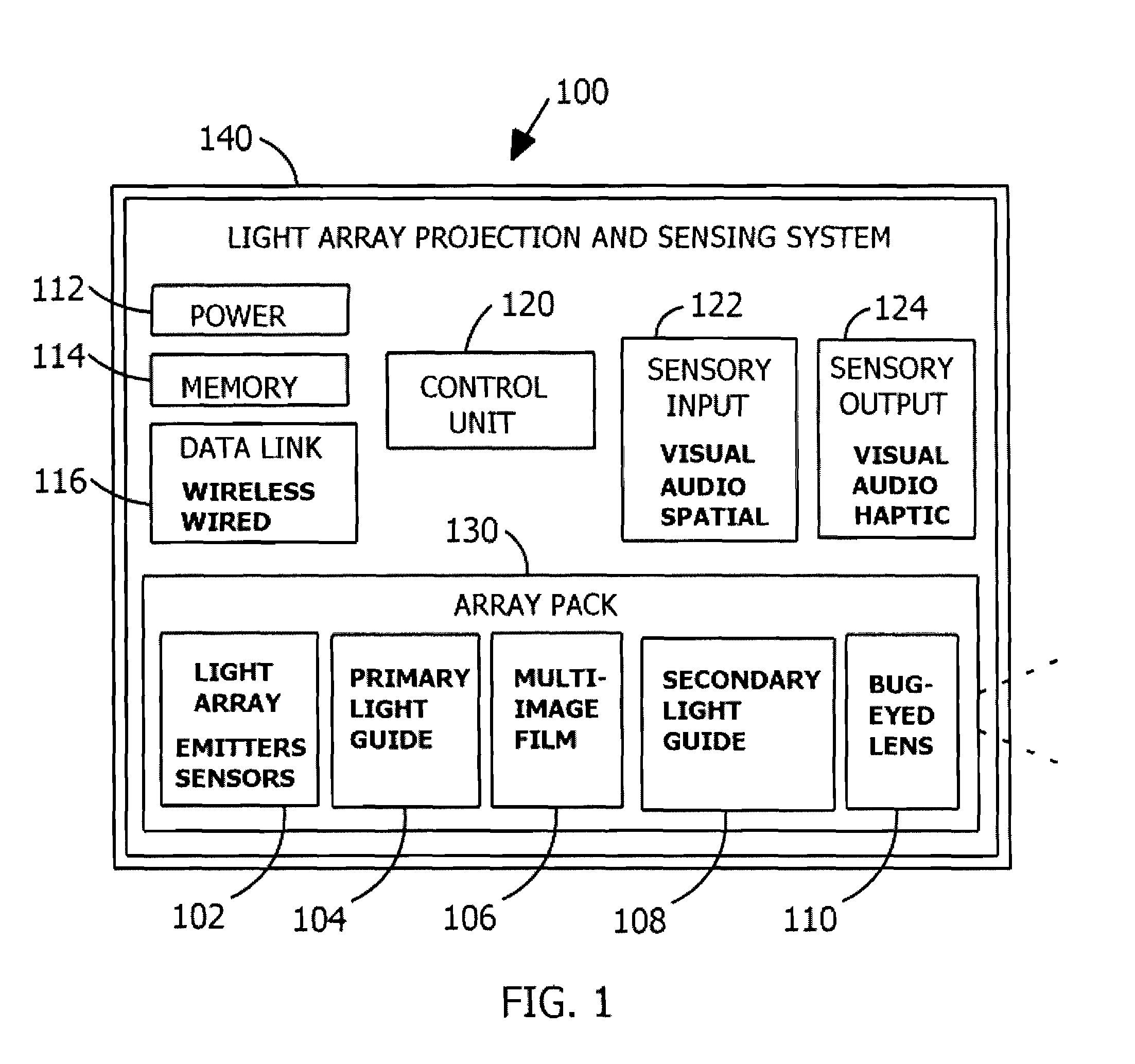
Light array projection and sensing system
a technology of sensing system and light array, which is applied in the field of light array projection and sensing system, can solve the problems of difficult to market mobile projection devices for a host of applications with wide consumer appeal, large-scale projection systems often cost thousands of dollars to illuminate graphic screens in public forums, and achieve the effect of enhancing visual effects and low cos
- Summary
- Abstract
- Description
- Claims
- Application Information
AI Technical Summary
Benefits of technology
Problems solved by technology
Method used
Image

Examples
first embodiment
rlaid Image Projection
[0172]So turning to FIGS. 16-18, thereshown is a section view of the array disk pack 230 positioned in front of the projection surface 250. FIGS. 16-18 represent three different temporal views of the array disk pack 230 in operation. Further, the array disk pack 230 is assumed to be operatively associated with a control unit and power source (not shown). In FIG. 16 can be seen a white LED 301, film image 341, convex lens 381, projection beam 336A, and illuminated image 338A. In FIG. 17 can be seen a white LED 300, film image 340, convex lens 380, projection beam 336B, and illuminated image 338B. And finally, in FIG. 19 can be seen a white LED 303, film image 343, convex lens 383, projection beam 336C, and illuminated image 338C. The film images 341, 340, and 343 are assumed to contain images of a dog (as shown earlier in FIG. 15).
[0173]To illuminate and animate an overlaid image, the light sources contained in the array disk pack 230 are turned on in sequence. ...
second embodiment
ar Array Pack
[0198]Referring back to FIGS. 19 and 20, the second embodiment essentially operates in the same manner as first embodiment. That is, even though the array disk pack of the first embodiment (not shown) was replaced with the planar array pack 430, no operational changes exist. Whereby, for the sake of brevity, the reader may refer to the first embodiment discussion regarding operation.
Third Embodiment—Overlaid Image Sensing Device with Sensing Array Pack
[0199]In FIGS. 27-28 an alternative third embodiment is shown, referred to as a light sensing device 600 having the capability to detect light images. The light sensing device 600 is similar in appearance and construction to the first embodiment. Whereby, in the third embodiment, similar reference numerals are utilized for common components with respect to the first embodiment shown in FIGS. 2-18.
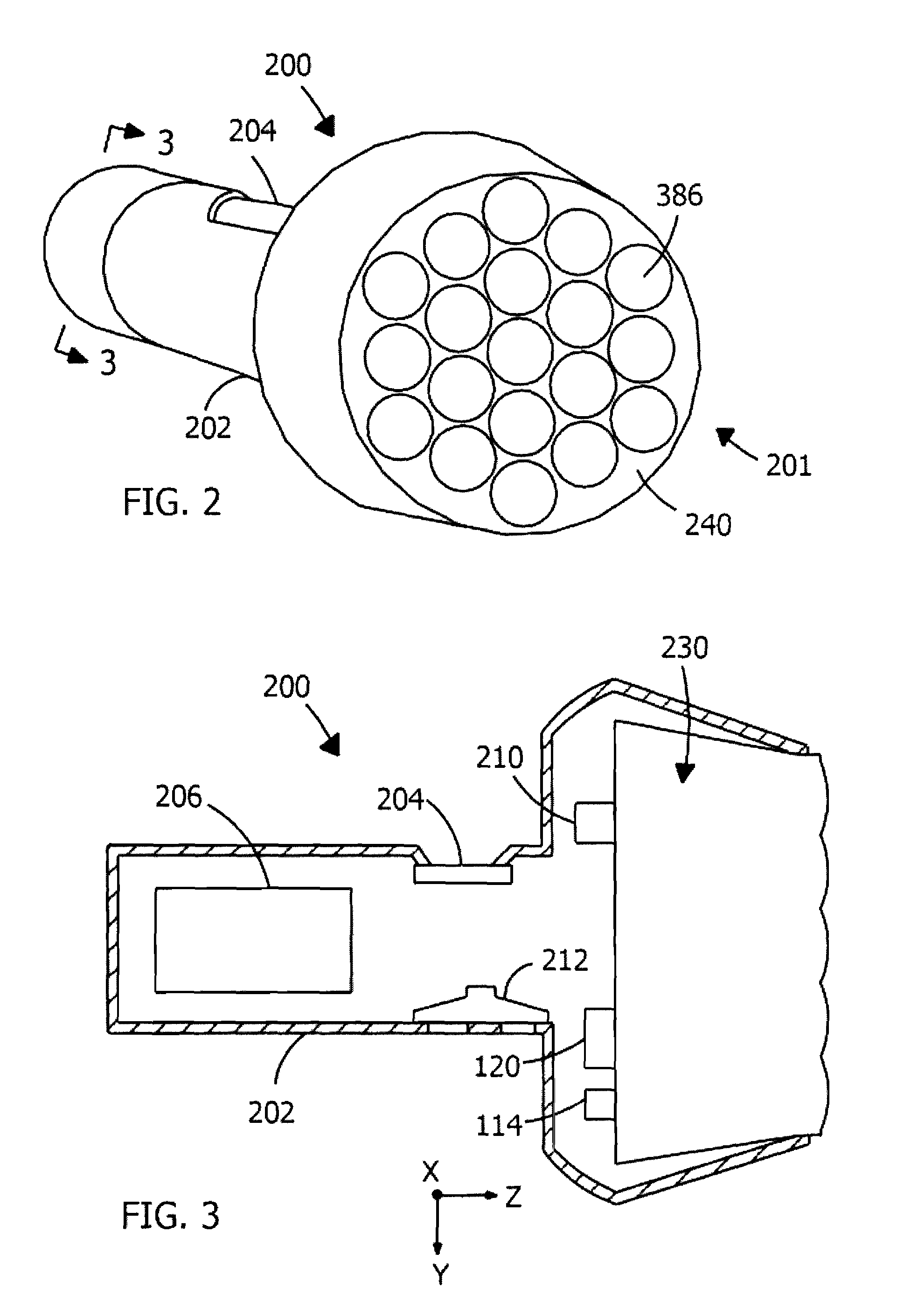
[0200]Thereshown in FIGS. 27-28, the light sensing device 600 has the shape of a flashlight that includes a handle 202 sized to ...
third embodiment
rlaid Image Sensing
[0203]So turning to FIGS. 31A, 31B, 31C thereshown is a section view of the sensing array pack 630 positioned in front of a projection surface 250. FIGS. 31A, 31B, 31C represent three different temporal views of the sensing array pack 630 in operation. Further, the sensing array pack 630 is assumed to be operatively associated with the control unit and power source (not shown). FIG. 31A shows an infrared LED 610, blank film image 640, convex lens 386, infrared photodiode 611, first bar film image 641, convex lens 381, reflected light ray 637A, and view region 638A. In FIG. 31B can be seen infrared LED 610, infrared photodiode 612, second bar film image 642, convex lens 380, reflected light ray 637B, and view region 638B. And finally, in FIG. 31C can be seen an infrared LED 610, infrared photodiode 613, third bar film image 643, convex lens 383, reflected light ray 637C, and view region 638C. The bar film images 641, 642, 643 are assumed to contain bar images and t...
PUM
 Abstract
Description
Claims
Application Information