Approach to make a high performance membrane electrode assembly (MEA) for a PEM fuel cell

a fuel cell and membrane electrode technology, applied in the field of electrochemical cells, can solve the problems of reducing the performance increasing the internal resistance of the fuel cell,

Active Publication Date: 2012-01-24
GM GLOBAL TECH OPERATIONS LLC
View PDF51 Cites 10 Cited by
  • Summary
  • Abstract
  • Description
  • Claims
  • Application Information

AI Technical Summary

Benefits of technology

[0034]Further, another advantage of the present invention relates to water management of the fuel cell. Typically, product water is generated in the fuel cell reaction and rejected at the cathode 106 where the water typically escapes by simple flow or by evaporation. However, means may be provided if desired, for collecting the water as it is formed to carry it away from the fuel cell 99. Good water management in the cell enables successful long-term operation of electrochemical fuel cell 99. Spatial variations of water content within the membrane 102 of a current-carrying fuel cell result from the electro-osmotic dragging of water with proton (H+) transport from anode 104 to cathode 106, the production of water by the oxygen reduction reaction at the cathode 104, humidification conditions of the inlet gas stream, and “back-diffusion” of water from cathode 106 to anode 104. It should be noted that for currently employed PEM membranes 102, preferred operational conditions to achieve optimum efficiency include a cathode 106 outlet relative humidity of 100% or greater. Previously, to achieve this humidity, both the anode 104 and cathode 106 reactant streams were externally humidified prior to entering the fuel cell 99, which necessitated humidification equipment. As will be discussed in greater detail below, one advantage of the present invention is a reduction and / or elimination of the need for external humidification of the cathode 106 and / or anode 104 inlet stream.

Problems solved by technology

Unfortunately, many metals are susceptible to corrosion in the hostile PEM fuel cell environment, and contact elements made therefrom either dissolve (e.g., in the case of aluminum), or form highly electrically resistive, passivating oxide films on their surface (e.g., in the case of titanium or stainless steel) that increases the internal resistance of the fuel cell and reduces its performance.

Method used


Image

  • Approach to make a high performance membrane electrode assembly (MEA) for a PEM fuel cell
  • Approach to make a high performance membrane electrode assembly (MEA) for a PEM fuel cell
  • Approach to make a high performance membrane electrode assembly (MEA) for a PEM fuel cell

Examples


Embodiment Construction

[0022]The following description of the preferred embodiments is merely exemplary in nature and is in no way intended to limit the invention, its application, or uses.

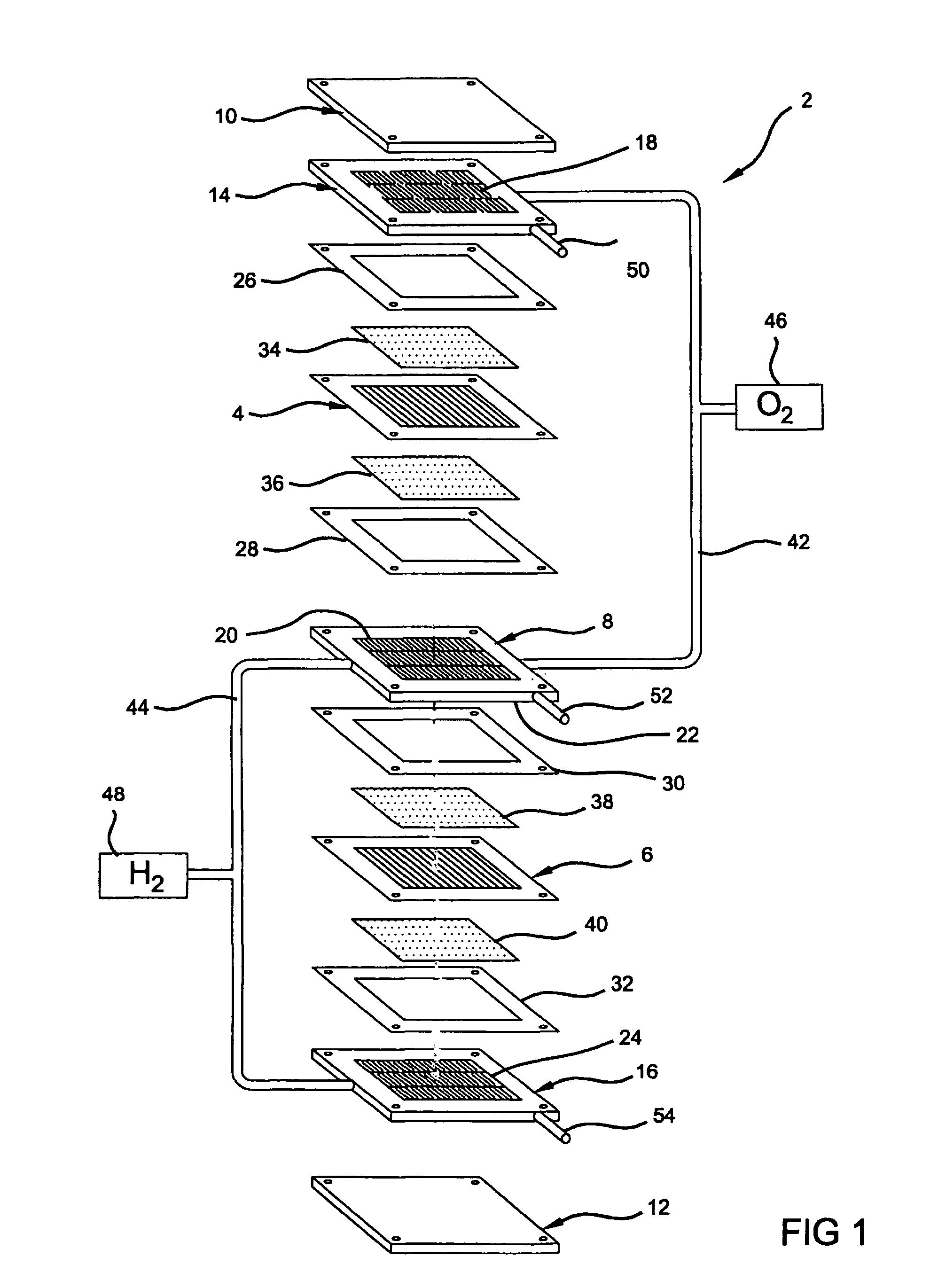
[0023]The present invention relates to an electroconductive fuel cell element, and more particularly to an improved fluid distribution media element for use in a fuel cell. For a better understanding of the present invention, a brief background is provided herein. FIG. 1 depicts a conventional two cell, bipolar fuel cell stack 2 having a pair of membrane-electrode-assemblies (MEAs) 4 and 6 separated from each other by an electrically conductive fluid distribution element 8, hereinafter bipolar plate 8. The MEAs 4 and 6 and bipolar plate 8, are stacked together between stainless steel clamping plates, or end plates 10 and 12, and end contact elements 14 and 16. The end contact elements 14 and 16, as well as both working faces of the bipolar plate 8, contain a plurality of grooves or channels 18, 20, 22, and 24, respectiv...


PUM

PropertyMeasurementUnit
thicknessaaaaaaaaaa
thicknessaaaaaaaaaa
thicknessaaaaaaaaaa

Abstract

An electrically conductive fluid distribution element for use in a fuel cell having a conductive non-metallic porous media having a surface with an electrically conductive metal deposited along one or more metallized regions. The metallized regions are arranged to contact a membrane electrode assembly (MEA) in a fuel cell assembly, and thus improve electrical conductance at contact regions between the MEA and the fluid distribution media. Methods of making such a fluid distribution element and operating fuel cell assemblies are also provided.

Description

FIELD OF THE INVENTION[0001]The present invention relates to electrochemical cells, and more particularly to electrically conductive fluid distribution elements and the manufacture and operation of fuel cells incorporating such fluid distribution elements.BACKGROUND OF THE INVENTION[0002]Fuel cells have been proposed as a power source for electric vehicles and other applications. One known fuel cell is the PEM (i.e., Proton Exchange Membrane) fuel cell that includes a so-called MEA (“membrane-electrode-assembly”) comprising a thin, solid polymer membrane-electrolyte having an anode on one face and a cathode on the opposite face. The anode and cathode typically comprise finely divided carbon particles, very finely divided catalytic particles supported on the internal and external surfaces of the carbon particles, and proton conductive material intermingled with the catalytic and carbon particles. The MEA is sandwiched between gas diffusion media layers and a pair of electrically cond...

Claims


Application Information

Patent Timeline
Patent Type & Authority Patents(United States)
IPC IPC(8): H01M2/14H01M8/04H01M8/10B32B3/26H01M8/02H01M4/96
CPCH01M8/0232H01M8/0234H01M8/0245Y02E60/50Y10T428/24999Y10T428/249986
Inventor MIKHAIL, YOUSSEF MVYAS, GAYATRI
Owner GM GLOBAL TECH OPERATIONS LLC
Why Eureka
Try Eureka