Electro-mechanical pulse generator

a pulse generator and electro-mechanical technology, applied in the direction of electric switches, electric apparatus, emergency protective devices, etc., can solve the problems of large number of parts, no self-cleaning properties, and the majority of electro-mechanical pulse generators are relatively complex, so as to achieve the effect of preventing rebound effects and mutual cleaning of contact surfaces

Active Publication Date: 2012-01-24
SONION SEE ATTACHED PAGE 3 OF 3
View PDF18 Cites 74 Cited by
  • Summary
  • Abstract
  • Description
  • Claims
  • Application Information

AI Technical Summary

Benefits of technology

[0010]It is an advantage of the invention that rotation of the first part in relation to the base will make the displaceable portion engage and slide along an outer surface of the electrical contacts from the first to the second position, whereby a mutual cleansing of the contact surfaces is obtained.
[0011]The protrusion on the base that is configured to prevent rebound of the displaceable portion is preferably arranged proximally to an outer peripheral surface of the base. The base preferably has a disc-shaped or cylindrical outer contour with the protrusion arranged along a circumferential section of the disc-shaped or cylindrical base. The cylindrical base preferably comprises a pie piece, or circle sector cut-out, with a flat bottom surface from which the protrusion projects in a direction along the axis of rotation.
[0012]The protrusion may comprise a top section and a pair of inclined surfaces leading down to a surface of the base, for example, a flat bottom surface in the circle sector cut-out. The pair of inclined surfaces are arranged to slidingly engage with the displaceable resilient displaceable portion.
[0013]According to a particularly advantageous embodiment of the invention, a distance, along the axis of rotation, between the top of a projection and a top of the protrusion is smaller than a cross-sectional dimension, such as a diameter, of the displaceable portion. This embodiment prevents a formation of an unintentional path through which the resilient displaceable displaceable portion can travel after it has engaged one of the electrical contacts (active electrical contact) and begins to revert towards a neutral or middle location between the two electrical contacts. The absence of such an unintentional path of travel towards an inactive electrical contact effectively prevents rebound effects.
[0014]Preferably, the displaceable portion extends outwardly and between the electrical contacts in order to ensure that the displaceable portion will engage these when a projection of the rotating first part moves the displaceable portion in either clock-wise or counter-clock-wise direction toward one of the electrical contacts. The size or extent of the electrically conductive elements ensuring that the displaceable portion remains engaged with the electrical contacts while sliding there along by the rotating projection.
[0015]In a preferred embodiment, the projections are positioned, in the plane of the rotation, in a uniform circular pattern around the axis of the rotational movement. In this manner, the projections will all be displaced along the same path, when the first part is actuated or rotated.

Problems solved by technology

Most of these electro-mechanical pulse generators are relatively complicated with a large number of parts and have no self-cleaning properties.

Method used


Image

  • Electro-mechanical pulse generator
  • Electro-mechanical pulse generator
  • Electro-mechanical pulse generator

Examples


second embodiment

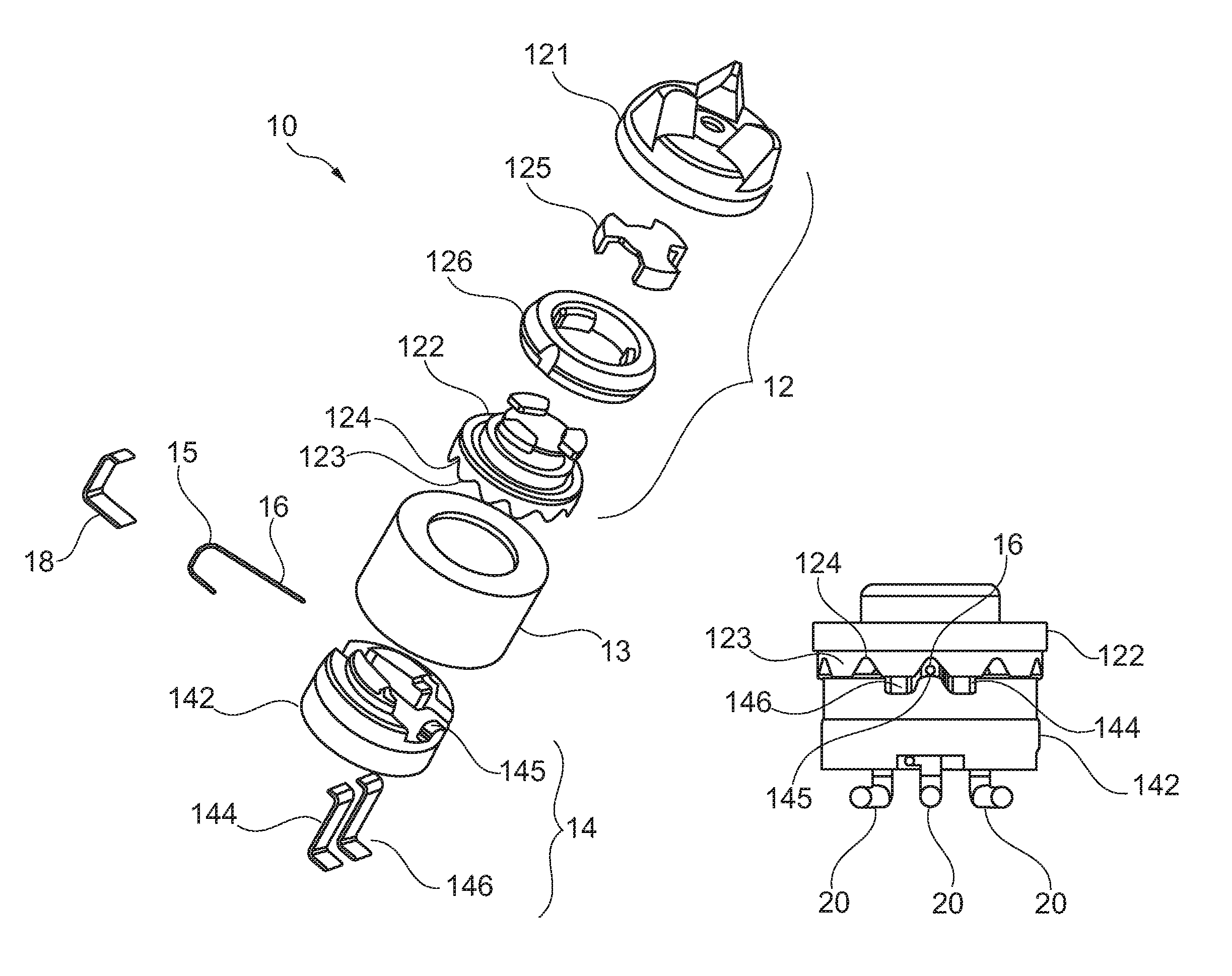
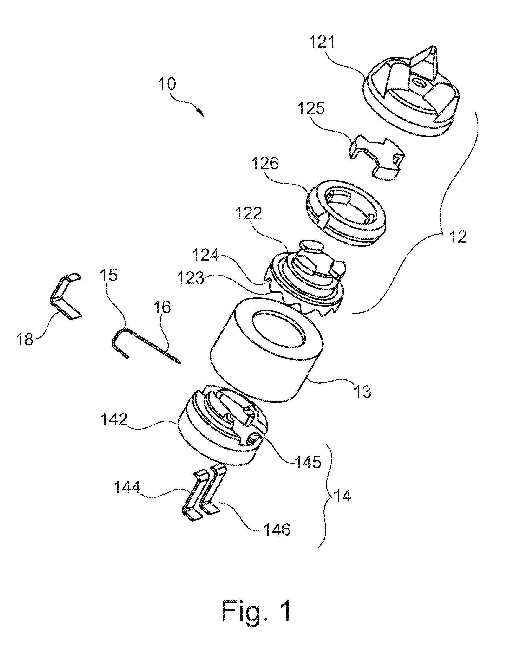
[0063]FIG. 3 is an exploded view of an electromechanical pulse generator 10 according to the invention. The design style of this pulse generator is often referred to as “roller key” or simply “roller”. Components of this embodiment that have similar functions to components of the pulse generator discussed in connection with FIG. 1 have been provided with identical reference numbers to ease comparison and understanding.

first embodiment

[0064]The first part 12 is provided as a unitary element, preferably an injection molded thermoplastic item, which provides the functionality of the actuatable knob 121, element 122 and intermediate members 125, 126 of the pulse generator of FIG. 1. A corrugated surface 130 of the first part 12 extends to the outside of mating housing portions 13 allowing the user to touch and actuate the pulse generator 10. The orientation of the corrugated surface 130 and shape and size of the first element 12 relative to the mating housing portions 13 allows the user to manipulate the first part 12 in transversal orientation relative to the axial direction of the pulse generator 10 through the centre of base 142 and first part 12. This actuation orientation is different from the one applied in pulse generator according to the invention (FIG. 1) where the actuation orientation of the knob 121 is axially.

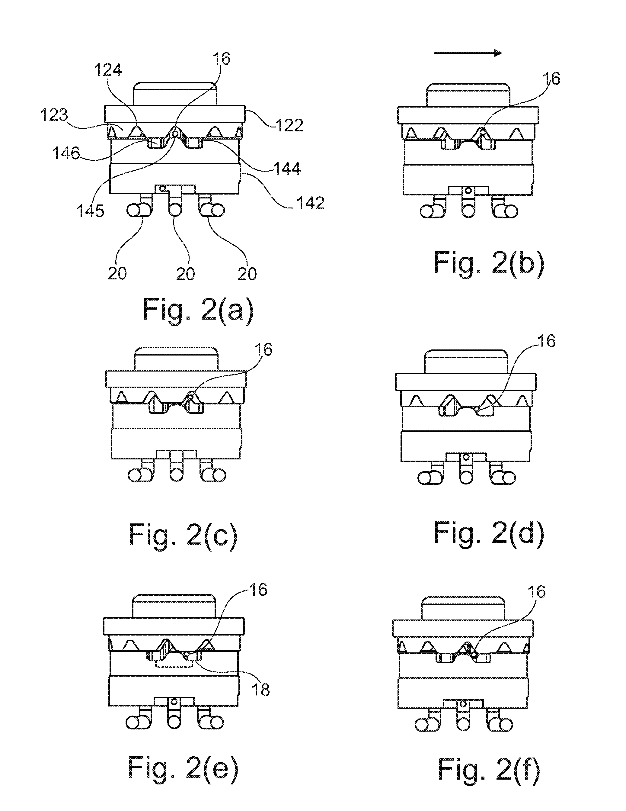
[0065]The base element 142 also comprises a protrusion 145 arranged proximally to an outer peri...


PUM


Abstract

An electromechanical pulse generator and a method of generating electrical pulses are disclosed. The electromechanical pulse generator comprises very few parts and includes an effective mechanism to prevent contact rebound. An upper, user-actuable and rotatable part has a surface with a plurality of projections. A lower part has an electrical conductor with a displaceable resilient contact portion biased against the projections and two electrical contacts positioned, in the plane of rotation, on either side of the displaceable contact portion.

Description

CROSS REFERENCE TO RELATED APPLICATION[0001]This application is related to and claims priority to U.S. Provisional Patent Application Ser. No. 61 / 125,092 filed Apr. 22, 2008, titled “An Electro-Mechanical Pulse Generator,” which is incorporated herein in its entiretyFIELD OF THE INVENTION[0002]The present invention relates to an electromechanical pulse generator and a method of generating electrical pulses. The electromechanical pulse generator comprises very few separate parts and includes an effective mechanism to prevent contact rebound during actuation.BACKGROUND OF THE INVENTION[0003]A number of different electro-mechanical pulse generators are disclosed in U.S. Pat. No. 5,380,965, U.S. Pat. No. 6,972,306, U.S. Pat. No. 6,943,308, DE 3025514 and DK-A-168,258. Most of these electro-mechanical pulse generators are relatively complicated with a large number of parts and have no self-cleaning properties. The electro-mechanical pulse generator disclosed in DE 3025514 lacks a mechani...

Claims


Application Information

Patent Timeline
Patent Type & Authority Patents(United States)
IPC IPC(8): H01H19/11
CPCH01H19/005H01H19/11H01H19/63H01H2019/006H01H2019/146H01H2300/004
Inventor ANDREASEN, JORGENRAVNKILDE, SORENLARSEN, PETER GORM
Owner SONION SEE ATTACHED PAGE 3 OF 3
Why Eureka
Try Eureka