Drop test apparatus

a test apparatus and drop technology, applied in the field of drop test apparatus, can solve the problems of losing the stability of unstable factor in the state of the drop of the test article, and unstable factor in the free fall condition, so as to improve the reproducibility of the test, raise the durability of the acceleration means, and improve the posture of the test article

Inactive Publication Date: 2009-02-05
HITACHI TECH & SERVICES
View PDF4 Cites 23 Cited by
  • Summary
  • Abstract
  • Description
  • Claims
  • Application Information

AI Technical Summary

Benefits of technology

[0022]According to the above-mentioned rebound prevention means, the rebound impact to be caused by the collision of the leaped-up test article with the landing surface again is prevented, and thus a certain single impact test becomes possible. The holding of the test article in the air by the rebound prevention means can always let the test article take the state to land on a landing surface with constant posture. Therefore, it becomes easy to hold the test article again automatically by the holder, and a complete automation of the repeat test becomes possible.
[0023]In the above-mentioned drop test apparatus, it is preferable to accelerate compulsively the holder by transmitting the driving force for compulsive acceleration by the acceleration means through a timing belt. By doing like this, lightening of the accelerating force transmission element can be aimed at, and the inertia load of the accelerating force transmission element for the acceleration means can be reduced. The durability of the acceleration means can be raised by such reduction of the load, and the durability to bear for the drop test repeated, for example, by several thousand times units about one test article can be realized.
[0024]It is preferable to install, in the holder, the holding unit for holding the test article and the posture maintenance unit that maintains the posture of the test article on the occasion of a release of the test article from the holding unit. The posture of the test article can be kept when the holding unit releases the test article, and the reproducibility of the test can be improved more.
[0025]In the above-mentioned drop test apparatus, it is preferable to install an impact-absorbing means, in the grasp unit, for absorbing a shock of the test article on the occasion that the grasp unit grasps the leaped-up test article. It can be effectively controlled that the impact of the test article affects directly to the grasp unit on the occasion of the grasp of the test article, and can improve the durability of the holding unit greatly.
[0026]According to the compulsion acceleration drop test of the present invention, the reproducibility of the test can be improved by avoiding the participation of the unstable factor, such as the frictional resistance, which happens when the test article drops, and it becomes possible to correspond to a higher drop test without scaling-up the apparatus.
[0027]According to the drop test apparatus having a rebound prevention means of the present invention, the rebound of the test article colliding with the landing surface can be effectively prevented, and thus a certain single impact test becomes possible, and a complete automation of the repeat test becomes possible.

Problems solved by technology

In these conventional methods wherein the test article in the holder is freely dropped, there is a problem to lose the stability of the free fall condition.
The stability of the free fall condition will be lost as the frictional resistance changes easily by the variations of the lubricity of the lubricant used to decrease the frictional resistance which is influenced, for instance, by such as the temperature atmosphere of the test place, and hence such change of the frictional resistance brings the unstable factor in the state of the drop of the test article.
There is a problem in the conventional methods, too, that the enlargement of the drop test apparatus is not avoided.
Such the rebound being a high uncertainty event repeatedly gives the uncertain impact to the test article, and hence becomes a factor to lose the reproducibility of the test.
Moreover, the rebound is a factor to obstruct the automation of the repetitive test.
The rebound, however, is an obstruction factor as for the automation of the test.

Method used


Image

  • Drop test apparatus
  • Drop test apparatus
  • Drop test apparatus

Examples


Embodiment Construction

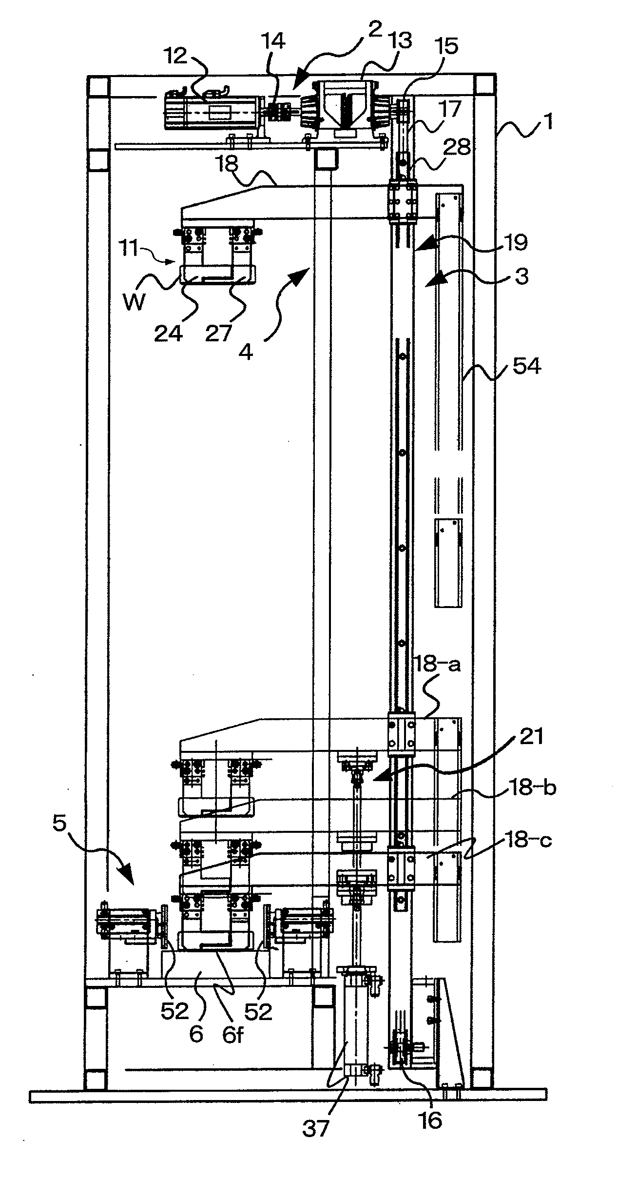
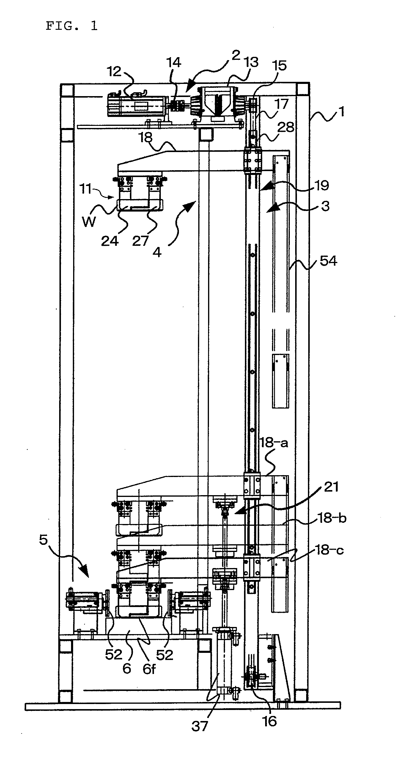
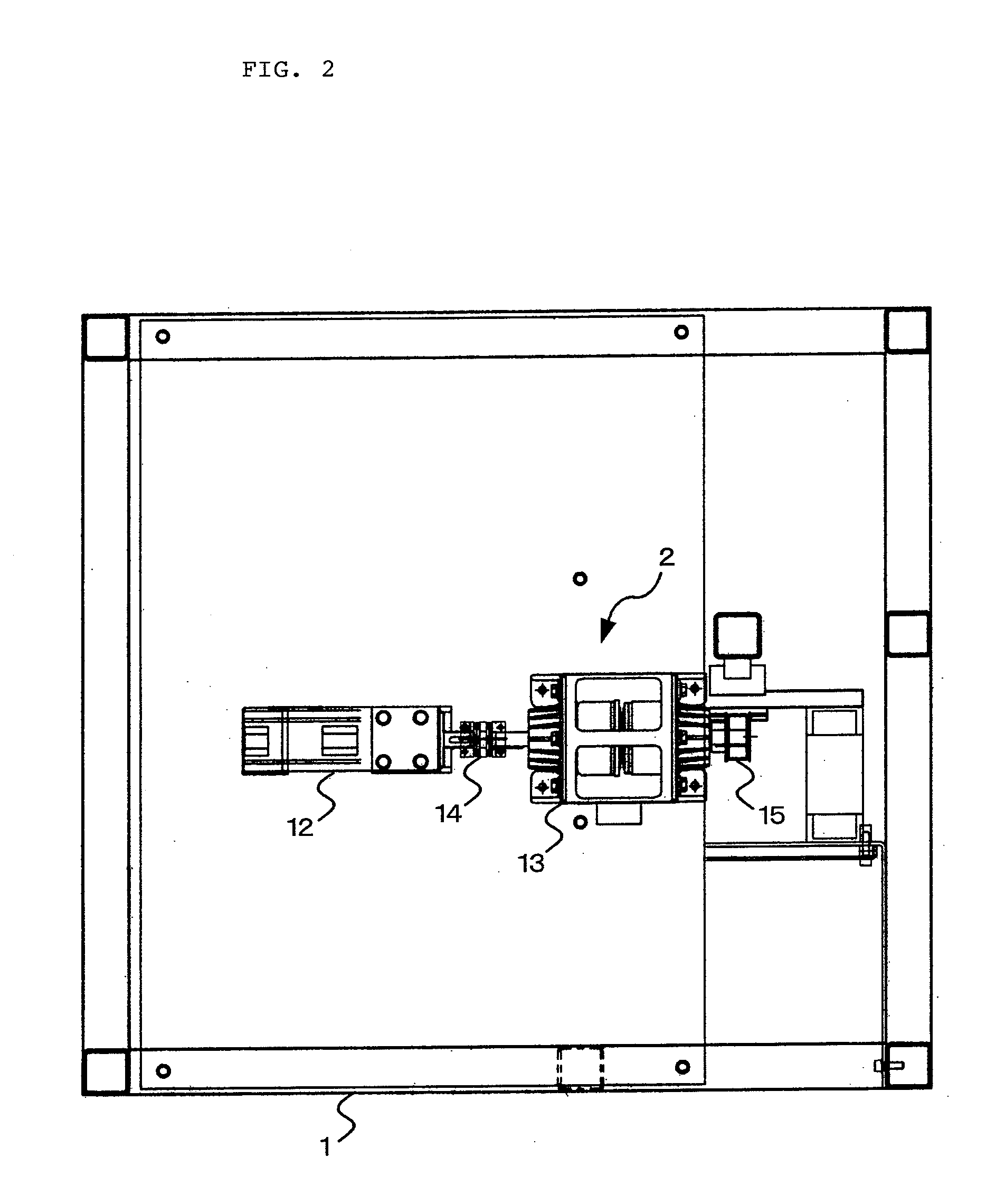
[0041]The embodiment of the present invention is described. Whole structure of one embodiment of the present invention is shown in FIG. 1 to FIG. 4. As shown in these FIG., the drop test apparatus is composed of, as the main element, acceleration means 2, accelerating force transmission 3, holding means 4, rebound prevention means 5, landing section 6, and control board 7 (FIG. 4), assembled in a frame body 1 formed in the shape of a vertically long and slim rectangular solid with steel materials. In FIG. 1 to FIG. 4, for avoiding complication, it is omitted to show a part of the components properly, and reference numerals are omitted arbitrarily.

[0042]The acceleration means 2 is assembled to the top part of the frame body 1, and works to compulsively accelerate the test article W held in the holder 11, which is one of the components of the holding means 4 explained later, toward the dropping direction of the test article up to the predetermined speed. The acceleration means 2 has a...


PUM

PropertyMeasurementUnit
heightaaaaaaaaaa
accelerationaaaaaaaaaa
speedaaaaaaaaaa

Abstract

Drop test apparatus, for performing a drop impact test by dropping an article to be tested on a landing surface in a free fall state and by colliding the article with the landing surface, is equipped with a holder for holding the article and an acceleration means for accelerating the holder. The holder with the article is accelerated in the dropping direction of the article by the acceleration means, and the article is released from the holder at the point when the holder is accelerated to a predetermined speed and is dropped to the landing surface. The reproducibility of the test can be enhanced due to an elimination of an unstable factor such as frictional resistance when the holder is dropped, and a higher test in a dropping height without scaling-up the apparatus can be achieved.

Description

TECHNICAL FIELD[0001]This invention relates to the drop test apparatus utilized for the drop test in freely dropping an article, such as portable equipment, to evaluate their reliability.BACKGROUND OF THE INVENTION[0002]Reliability to the dropping impact is strongly requested in portable equipments such as cellular phones and mobile type portable terminals that may happen while carrying. In manufacturers fabricating the portable equipments and parts thereof, therefore, the reliability to the dropping impact is evaluated by repeating the drop test, which evaluates the influence of the dropping impact, and is performed by colliding the portable equipment and the part thereof with the landing surface in the state of a free fall, and also the design data on the dropping impact tendency is obtained. In such drop test, it is usual for the manufacturers of the portable equipment to test the portable equipment as the test article, and, for the parts manufacturers, it is usual to test parts ...

Claims


Application Information

Patent Timeline
Patent Type & Authority Applications(United States)
IPC IPC(8): G01N3/303
CPCG01N3/303
Inventor FUKUSHIMA, SHINJIKURAHARA, SHUICHI
Owner HITACHI TECH & SERVICES
Why Eureka
Try Eureka