Fluidtight connector and connector assembly

a technology of connectors and connector assemblies, applied in the direction of securing/insulating coupling contact members, coupling device connections, electrical devices, etc., can solve problems such as problems such as an increased number of parts, and achieve the effects of preventing backlash, reliably preventing abrasion of terminals, and preventing backlash

Active Publication Date: 2009-06-30
SUMITOMO WIRING SYST LTD
View PDF5 Cites 23 Cited by
  • Summary
  • Abstract
  • Description
  • Claims
  • Application Information

AI Technical Summary

Benefits of technology

[0013]The seal of the resilient member closely contacts the receptacle and the outer surface of the inner housing to provide sealing therebetween when the fluidtight connector is connected properly with the mating connector. Additionally, the backlash preventing portions are compressed resiliently between the flange and the facing wall and the resilient forces of the backlash preventing portions press the inner housing forward with respect to the connecting direction with the mating connector to prevent backlash in forward and backward directions. One resilient member includes the seal for sealing between the connectors and the backlash preventing portions for preventing backlash between the connectors. In this way, the number of parts is reduced as compared with the case where these are separate parts.
[0035]Accordingly, the connector assembly has a high connection reliability of terminals even if placed in an environment subject to vibration.

Problems solved by technology

However, this construction requires the coil springs for suppressing the backlash between the connectors in addition to the waterproof packing for sealing between the connectors, thereby presenting a problem of an increased number of parts.

Method used


Image

  • Fluidtight connector and connector assembly
  • Fluidtight connector and connector assembly
  • Fluidtight connector and connector assembly

Examples


first embodiment

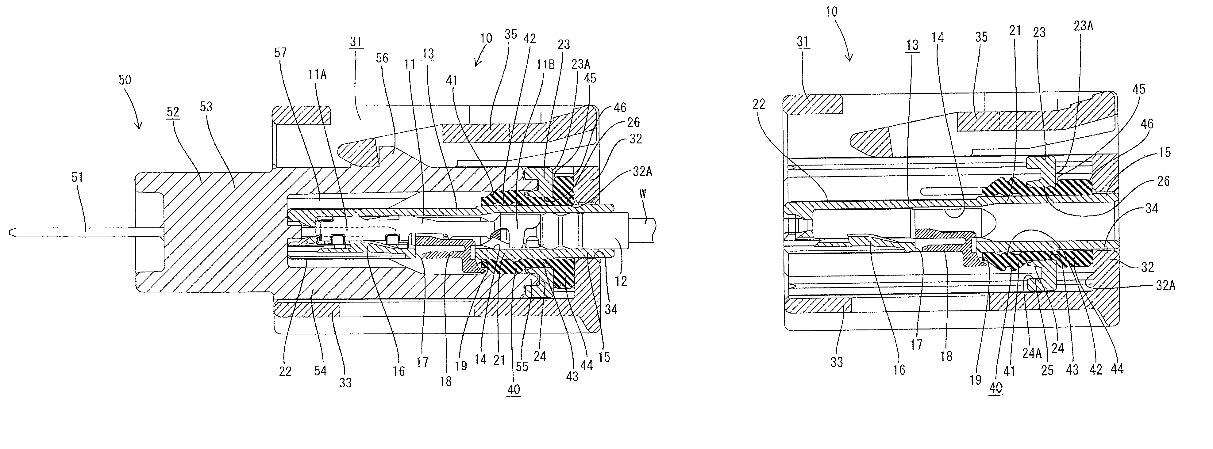
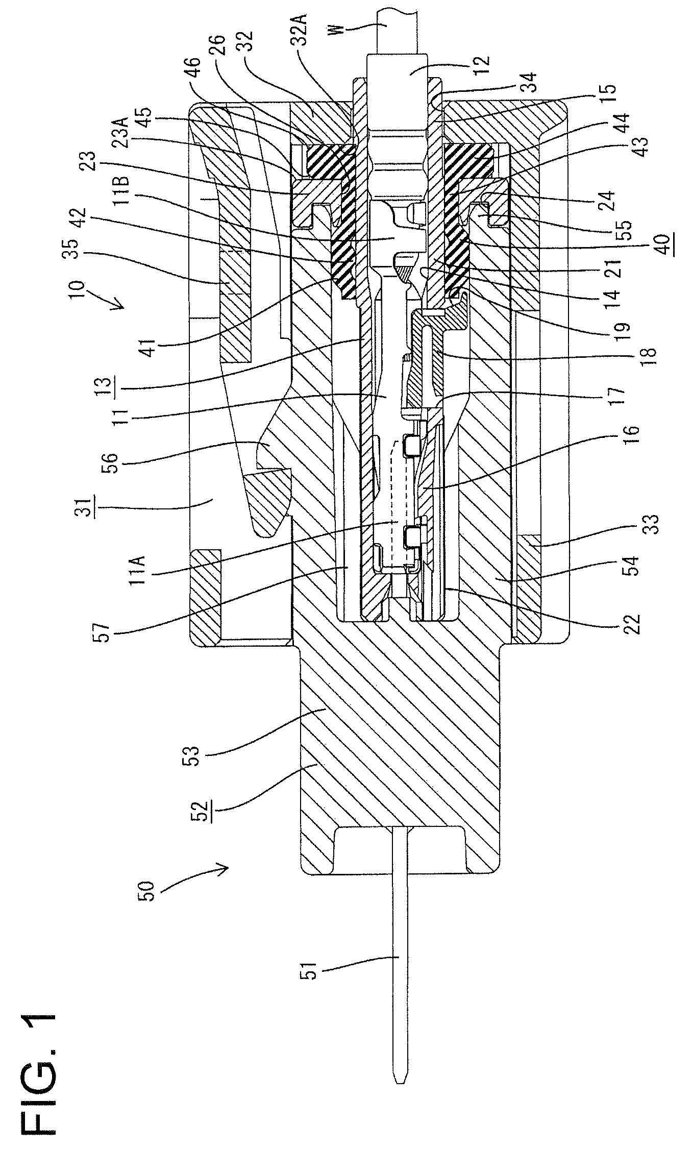
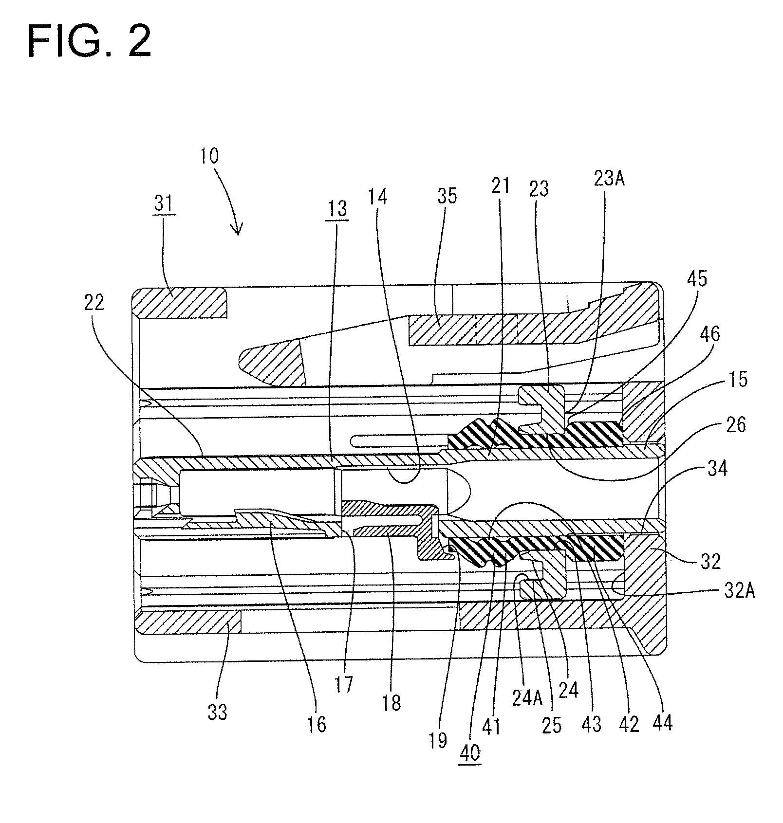
[0046]A watertight connector according to the invention is illustrated in FIGS. 1 to 6 and includes a female connector 10 that is connectable with a male connector 50. In the following description, ends of the connectors to be connected are referred to as the front ends and reference is made to FIG. 1 concerning the vertical direction.

[0047]The male connector 50 has male terminals 51 that are long in forward and backward directions and a male housing 52 for holding the male terminals 51. The male housing 52 is made e.g. of synthetic resin and includes a terminal holding portion 53 for holding the male terminals 51. A forwardly open substantially tubular receptacle 54 projects forward from the periphery the terminal holding portion 53 and is slightly wider than long. The male terminals 51 extend through the terminal holding portion 53 in forward and backward directions and project into the receptacle. A substantially ring-shaped annular rib 55 projects forward from the open front end...

second embodiment

[0086]A connector assembly according to the invention includes a male connector 110 and a female connector 120 that are connectable with each other as shown in FIGS. 7 to 9. In the following description, ends of the connectors 110, 120 to be connected are referred to as front ends and reference is made to FIG. 7 concerning vertical direction.

[0087]The male connector 110 has two male terminals 111 and a male housing 112 for holding the male terminals 111. The male housing 112 is made e.g. of synthetic resin and includes a terminal holding portion 113 for holding the male terminals 111 in forward and backward directions. A receptacle 114 projects forward in a connecting direction with the other connector from the periphery of the terminal holding portion 113. The terminal holding portion 113 has a wide rectangular shape (see FIG. 8) when viewed from the front.

[0088]The receptacle 114 is a forwardly open tube, and a ring-shaped annular rib 115 projects forward at opening front end of t...


PUM


Abstract

A watertight connector has a rubber member (40) mounted on an inner housing (13), and this rubber member (40) includes a sealing portion (41) substantially in the form of a tube fittable on the outer circumferential surface of the inner housing (13) before a flange (23), legs (43) integral to the sealing portion (41) and shaped to be insertable backward through pass-through openings (26), and backlash preventing portions (44) integral to the legs (43), shaped to be engageable with the peripheral edges of the pass-through openings (26) from behind and arranged between the flange (23) and a facing wall (32).

Description

BACKGROUND OF THE INVENTION[0001]1. Field of the Invention[0002]The invention relates to a fluidtight connector provided with a sealing member and to a connector assembly.[0003]2. Description of the Related Art[0004]U.S. Pat. No. 7,066,747 discloses a watertight connector with a seal for sealing between the watertight connector and a mating connector. The watertight connector has an inner housing and an outer housing is assembled to be relatively slidable in forward and backward directions along a connecting direction with the mating connector. A waterproof packing (seal) is mounted on the front end of the inner housing and is squeezed between the inner housing and a receptacle of the mating connector to provide sealing therebetween when the watertight connector is connected properly with the mating connector.[0005]Two metallic coil springs are provided in the above-described connector to prevent backlash between the connectors due to vibration or the like. The coil springs are moun...

Claims


Application Information

Patent Timeline
Patent Type & Authority Patents(United States)
IPC IPC(8): H01R13/40
CPCH01R13/5208H01R13/6272
Inventor MORIKAWA, SATOSHIHATA, TAKAOITOU, TOMONARI
Owner SUMITOMO WIRING SYST LTD
Why Eureka
Try Eureka