Breaking device for a dual bearing reel

a dual-bearing, breaking device technology, applied in the direction of reels, domestic cooling devices, lighting and heating devices, etc., can solve the problems of easy backlash, tension on the fishing line, and mechanical braking devices only generating proportional braking force, so as to prevent backlash and stabilize the attitude of the lure

Active Publication Date: 2006-01-10
SHIMANO INC
View PDF11 Cites 25 Cited by
  • Summary
  • Abstract
  • Description
  • Claims
  • Application Information

AI Technical Summary

Benefits of technology

[0010]An object of the present invention is to provide a braking device in a dual bearing reel that can prevent backlash, stabilize the attitude of the lure, and allow the lure to be cast farther.

Problems solved by technology

However, mechanical braking devices only generate braking force in proportion to the rotational speed of the rotor or the square of the rotational speed, regardless of whether or not there is tension on the fishing line.
Tension on the fishing line will gradually decrease from a point close to the maximum rotational speed of the spool, and thus backlash can easily occur.

Method used


Image

  • Breaking device for a dual bearing reel
  • Breaking device for a dual bearing reel
  • Breaking device for a dual bearing reel

Examples


second embodiment

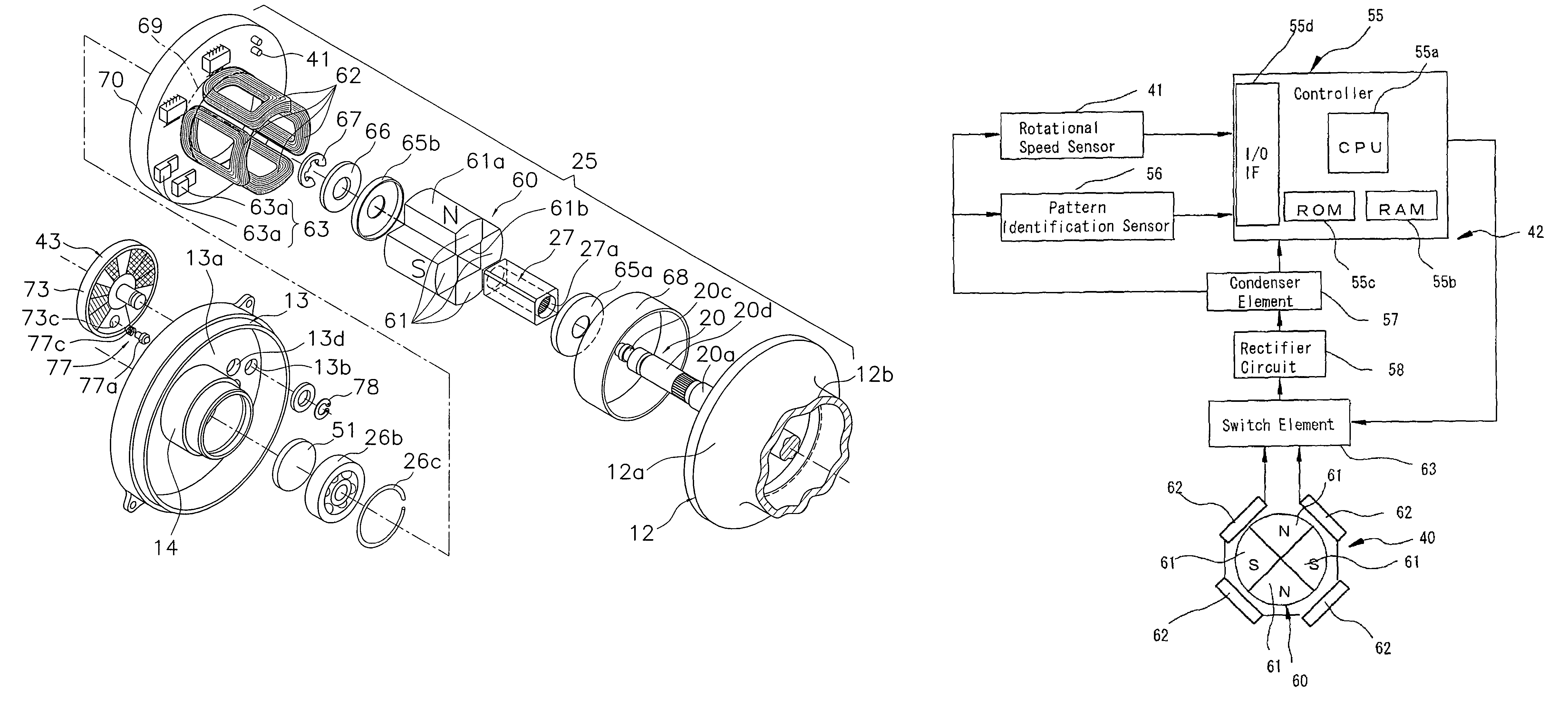
[0122]In the first embodiment, the first braking process is modified depending on the rotational speed V of the spool 12. In the second embodiment, the spool 12 is braked at a constant duty ratio regardless of the rotational speed of the spool 12, if the rotational speed of the spool 12 is greater than a predetermined value. Next, the brake control operation of the controller 55 during casting will be explained with reference to the control flow chart shown in FIG. 12.

[0123]Initialization occurs at Step S41 when the spool 12 rotates due to casting, electric power is stored in the condenser element 57, and an electric power supply flows into the controller 55. Since the processes from Step S41 through Step S43, from Step S47 through Step S49, and from Step S61–63 are the same as those of Step S1 through S3 and Step S7 through S9, and from Step S21–23, explanation thereof will be omitted herein.

[0124]In Step S44, the rotational speed V of the spool 12 is detected based on the pulses f...


PUM


Abstract

A spool braking device for a dual bearing reel includes a spool brake unit, a spool control unit, and a tension detection unit that includes a rotational speed sensor. The spool control unit is arranged between a spool and a reel body, and it an electrically controllable unit that controls the spool. The tension detection unit detects the tension applied to fishing line that is released from the spool during casting. The spool control unit electrically controls the spool braking unit so that the spool braking unit brakes the spool with a first braking force of 50 to 100% of the maximum braking force during a first predetermined time period when the tension detected by the tension detection unit is at or below a first predetermined value.

Description

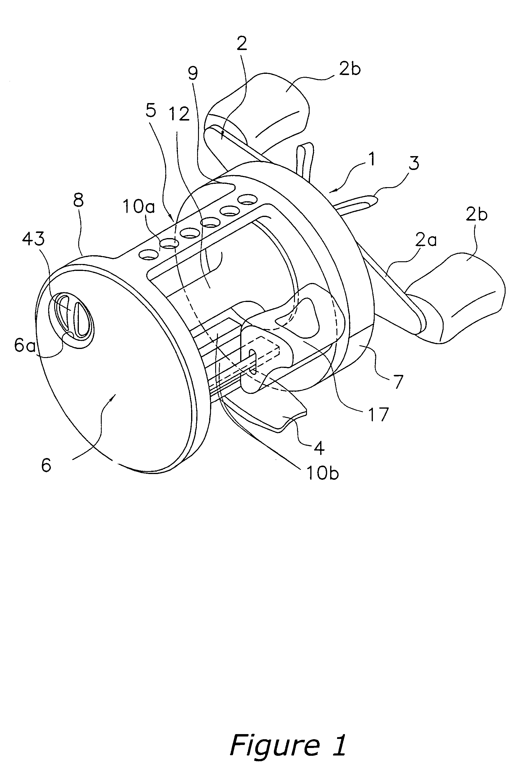
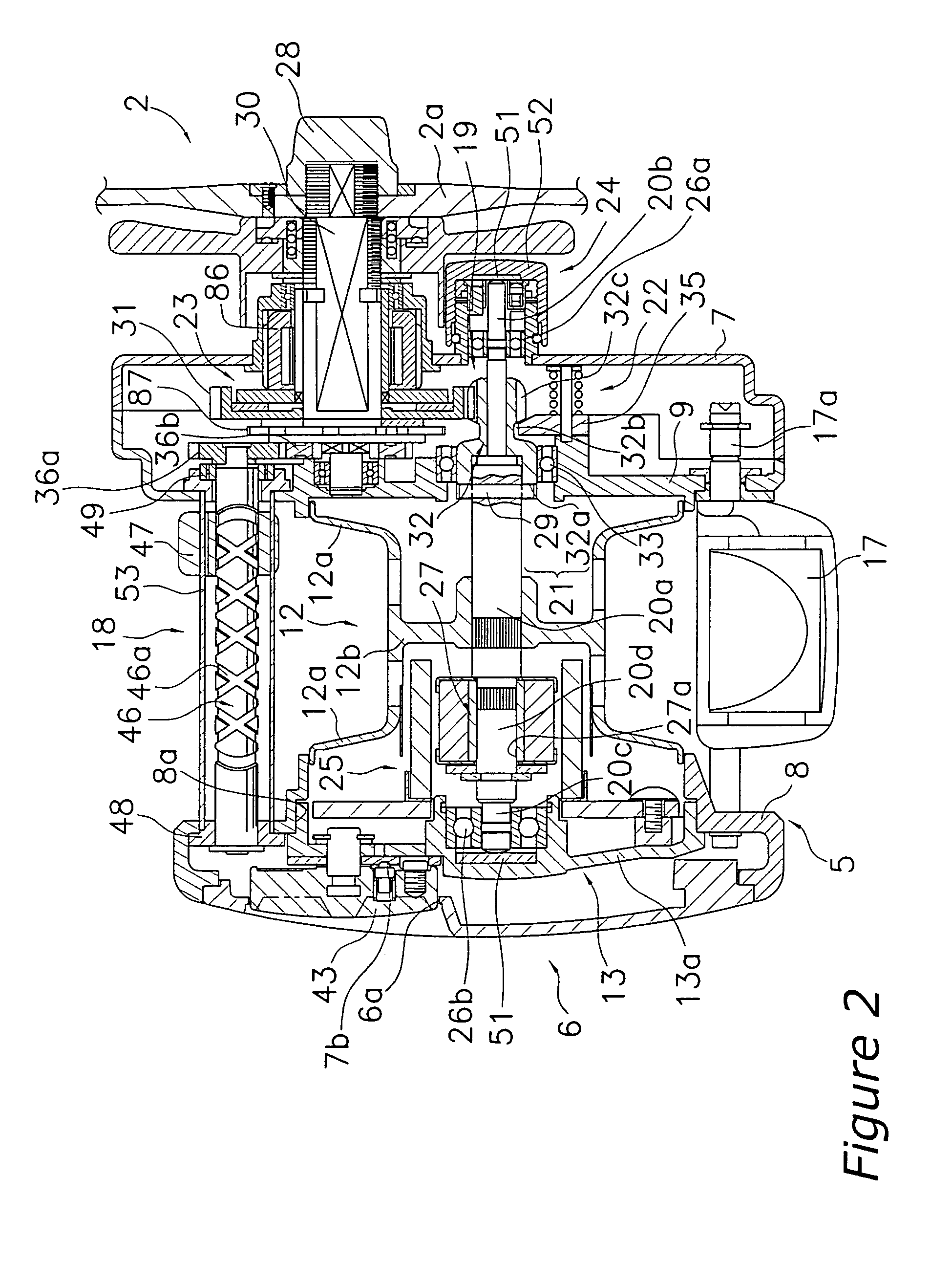
BACKGROUND OF THE INVENTION[0001]1. Field of the Invention[0002]The present invention relates to a braking device. More specifically the present invention relates to a braking device for a dual bearing reel that brakes a spool rotatively mounted to a reel unit.[0003]2. Background Information[0004]A braking device is conventionally provided in dual bearing reels in order to brake the spool, and in particular is provided in bait casting reels in which a lure or the like is mounted to the end of a fishing line and cast. The braking device prevents backlash during casting. Many of these conventional braking devices are mechanical type braking devices, which use centrifugal force or magnetic force. However, mechanical braking devices only generate braking force in proportion to the rotational speed of the rotor or the square of the rotational speed, regardless of whether or not there is tension on the fishing line. Thus, mechanical braking devices sometimes generate braking force even at...

Claims


Application Information

Patent Timeline
Patent Type & Authority Patents(United States)
IPC IPC(8): A01K89/02A01K89/0155
CPCA01K89/01555F25D23/069F25D2323/06F25D2201/10
Inventor IKUTA, TAKESHIKAWASAKI, KEN'ICHIHIRAIZUMI, KAZUKI
Owner SHIMANO INC
Why Eureka
Try Eureka