Display device

a technology of display device and liquid crystal, applied in the direction of optical light guide, instruments, optics, etc., can solve the problems of deformation of light guide plate, concentrated force on the extended portion of the optical sheet, and deterioration of the display quality of the liquid crystal display device, so as to prevent damage to the optical sheet and occurrence of wrinkles

Active Publication Date: 2012-01-05
JAPAN DISPLAY INC +1
View PDF3 Cites 24 Cited by
  • Summary
  • Abstract
  • Description
  • Claims
  • Application Information

AI Technical Summary

Benefits of technology

[0012]The present invention has been made in view of the above-mentioned problems, and it is therefore an object of the p

Problems solved by technology

However, the light guide plate is formed of a transparent member made of an acrylic resin or the like, and hence there is a problem in that the light guide plate is chipped off because of rubbing between the end portion of the metal frame and the light guide plate due to vibration, and in a case where the chips enter the illumination surface illuminated with the backlight, a display quality of the liquid crystal display device is deteriorated.
Further, when compared to the metal frame, the light guide plate made of a resin material has a larger coefficient of thermal expansion,

Method used


Image

  • Display device
  • Display device
  • Display device

Examples


embodiment 1

[Entire Configuration of Backlight Device]

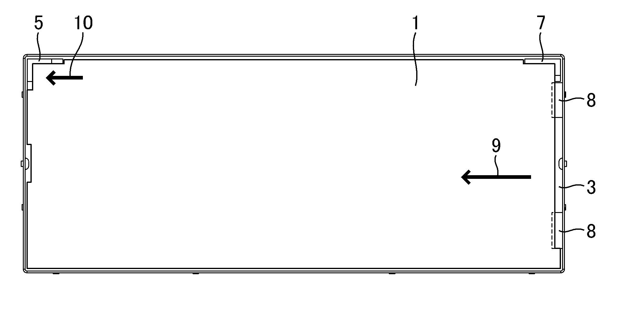
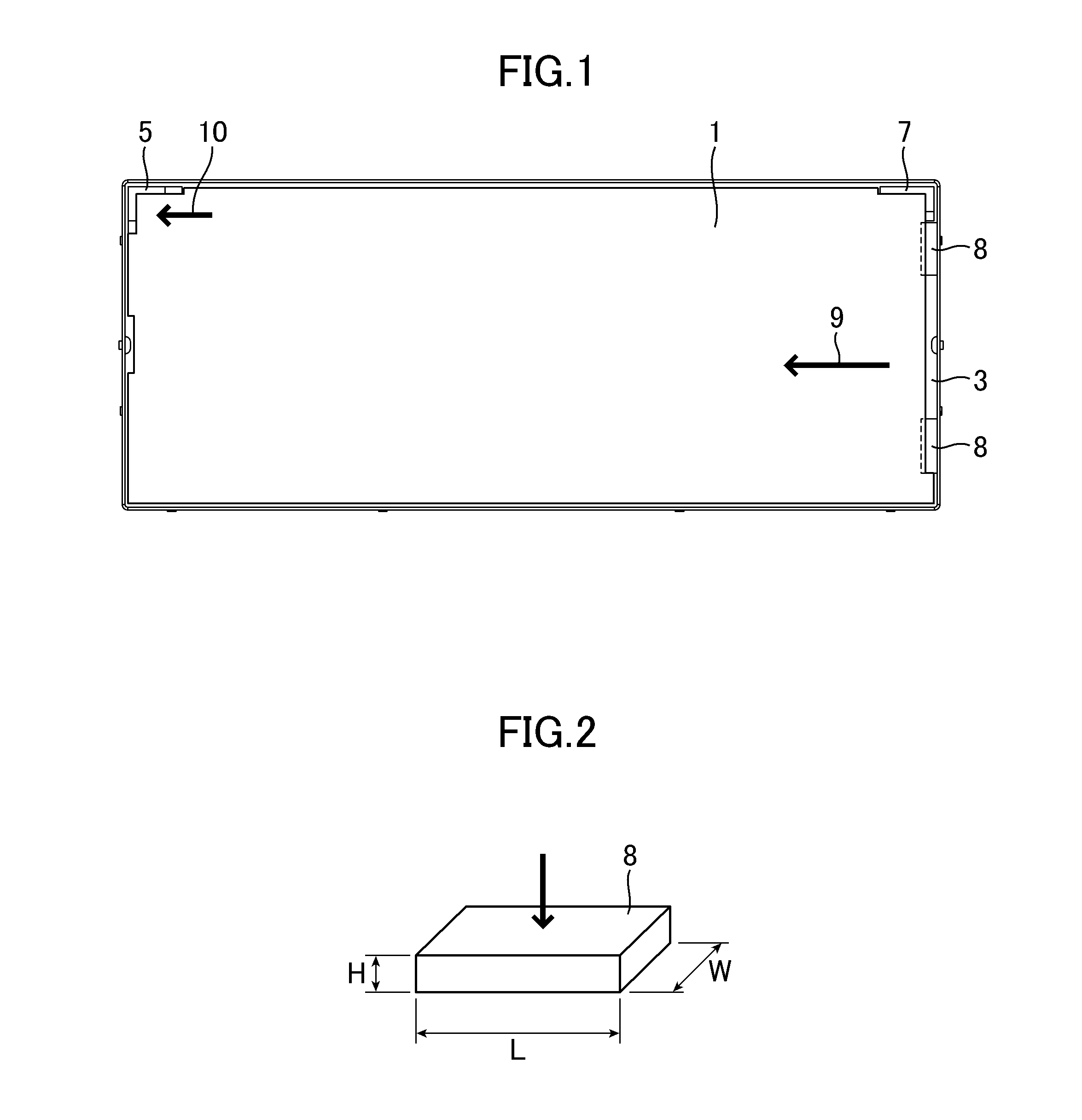
[0039]FIG. 1 is a top view illustrating a schematic configuration of a backlight device of a display device according to Embodiment 1 of the present invention, and more particularly, a view illustrating a fixed structure of a light guide plate of the backlight device according to Embodiment 1. Note that, an upper frame arranged on an illumination side of backlight and fitted to a lower frame, and an optical sheet arranged on an illumination side of the light guide plate are omitted.

[0040]As is apparent from FIG. 1, the display device according to Embodiment 1 is an in-car display device that has long sides longer than short sides, in other words, has a display region with a higher aspect ratio than an aspect ratio (16:9) of a wide screen. However, the invention of the subject application is not limited to the display device with a high aspect ratio, but is also applicable to a display device with another aspect ratio.

[0041]Further, in the ba...

embodiment 2

[0077]FIG. 14 is a top view illustrating a schematic configuration of a backlight device of a display device according to Embodiment 2 of the present invention. Note that, the backlight device according to Embodiment 2 has a similar configuration to that of Embodiment 1 except for a configuration of a mold member 6 arranged at a center portion in the longitudinal direction of the backlight device. Therefore, in the following description, the configuration of the mold member 6 is described in detail. Further, in FIG. 14, the upper frame that is fitted to the lower frame 3 to sandwich the optical sheet 4 and the light guide plate 1 from the illumination direction of the backlight is omitted.

[0078]As is apparent from FIG. 14, in the backlight device according to Embodiment 2, at the center portion of the side wall of the lower frame 3 in the longitudinal direction on the upper side of FIG. 14, the mold member 6 for supporting the light guide plate 1 from the top surface (illumination s...

embodiment 3

[0084]FIG. 17 is an exploded perspective view illustrating an entire configuration of a liquid crystal display device as a display device according to Embodiment 3 of the present invention. The display device according to Embodiment 3 has a similar configuration to that of a conventional liquid crystal display device except for the configuration of the backlight device. Note that, in the following description, a case of using the backlight device according to Embodiment 1 is described, but the backlight device according to Embodiment 2 is also applicable. Further, also in the following description, for ease of description, a light source, a reflective sheet, and the like, which are provided similarly in the conventional configuration, are omitted.

[0085]As illustrated in FIG. 17, the liquid crystal display device according to Embodiment 3 includes: the light guide plate 1 and the plurality of optical sheets 4, which are arranged sequentially; the lower frame 3, which has a surface th...


PUM


Abstract

Provided is a display device, including: a first protrusion formed to an inner side surface of one of side walls of the frame on a short side of an angled corner portion surrounded by the side walls; a second protrusion formed to an inner side surface of one of the side walls on a long side of the angled corner portion; and a third protrusion formed at another angled corner portion on another end side of at least one of the side walls sharing the angled corner portion provided with the first and second protrusions, and formed to an inner side surface of one of the side walls that is opposed to the side wall to which the first protrusion and/or the second protrusion are/is arranged, the optical sheet including cut-out first to third recesses which are to be fitted to the first to third protrusions.

Description

CROSS-REFERENCE TO RELATED APPLICATION[0001]The present application claims priority from Japanese application JP 2010-148569 filed on Jun. 30, 2010, the content of which is hereby incorporated by reference into this application.BACKGROUND OF THE INVENTION[0002]1. Field of the Invention[0003]The present invention relates to a display device.[0004]2. Description of the Related Art[0005]In recent years, along with an improvement of display performance of a liquid crystal display device, a display device is being actively used as an in-car display device. However, the in-car display device needs to cope with an environment for use of a car and to allow use under high temperature and low temperature, and is required to operate in a wide temperature range (use temperature range). Similarly, the in-car display device is required to have high vibration resistant performance so as to prevent looseness of assembly of components from occurring along with vibration of a car and the like.[0006]A...

Claims


Application Information

Patent Timeline
IPC IPC(8): G02F1/1333
CPCG02B6/0088G02F2201/54G02F2001/133317G02F1/133308G02F1/133317
Inventor WATANABE, SABURO
Owner JAPAN DISPLAY INC
Why Eureka
Try Eureka