System and method for monitoring and managing energy performance

a technology of energy performance and management system, applied in the direction of wind energy generation, mechanical power/torque control, electric devices, etc., can solve the problems of large energy consumption in facilities such as buildings, millions of dollars per year in energy consumption, and the situation may have already changed

Active Publication Date: 2012-01-24
NOVEDA TECH
View PDF4 Cites 60 Cited by
  • Summary
  • Abstract
  • Description
  • Claims
  • Application Information

AI Technical Summary

Problems solved by technology

Energy usage in facilities, such as buildings, is a large expense.
In a campus environment including many buildings, energy usage can cost millions of dollars per year.
Managing these costs so that energy costs are minimized while maintaining acceptable performance is a challenge.
By the time this process is finished, the building conditions may have already changed, making the gathered data not representative of current conditions and decisions based on the data untimely.
Thus, known EMSs do not provide the energy and operations information for a facility needed to determine the energy performance of the facility, and further provide that adequate monitoring of facility operations can be performed and appropriate actions can be taken based on the energy performance determinations.
The failings of the prior art are manifest in numerous real world deficiencies.
For example, without real time information that accounts for the large number of variables associated with energy management, which may include thermostat settings, energy usage from devices such as computers, sun height related to seasonality, cloud cover, external temperature and overall energy demand in the energy grid, understanding of energy flow is compromised.

Method used


Image

  • System and method for monitoring and managing energy performance
  • System and method for monitoring and managing energy performance
  • System and method for monitoring and managing energy performance

Examples


Embodiment Construction

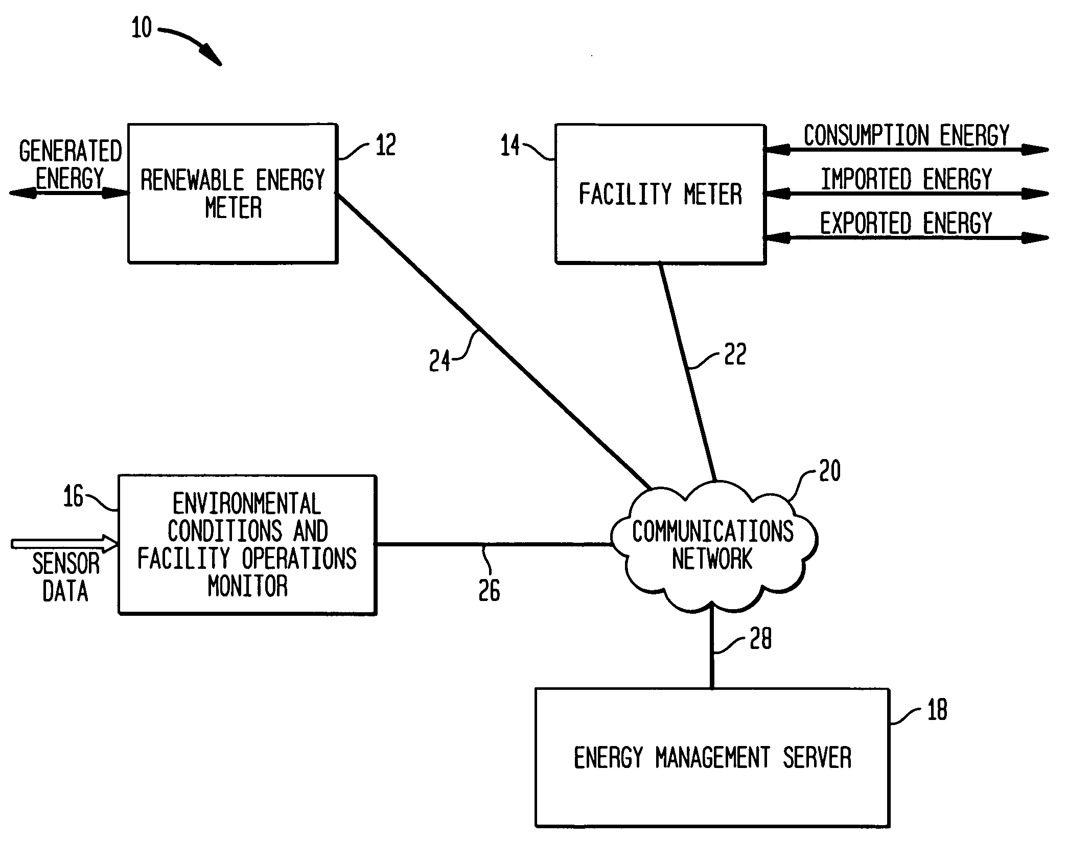
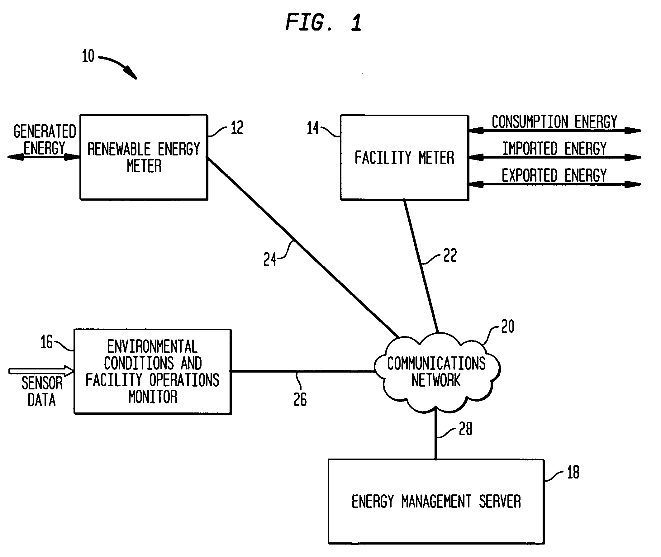
[0023]FIG. 1 is an exemplary system 10 for managing energy performance of a facility, in accordance with an aspect of the present invention. Referring to FIG. 1, the system 10 may include a renewable energy meter 12, a facility meter 14 and an environmental conditions and facility operations monitor 16, each of which has communications capabilities and can be communicatively coupled to an energy management server 18 over a communications network 20, such as the Internet. Communication links 22, 24, 26 and 28, which may be wireless or wired, can be established between the network 20 and the meters 12, 14, the monitor 16 and the server 18, respectively.

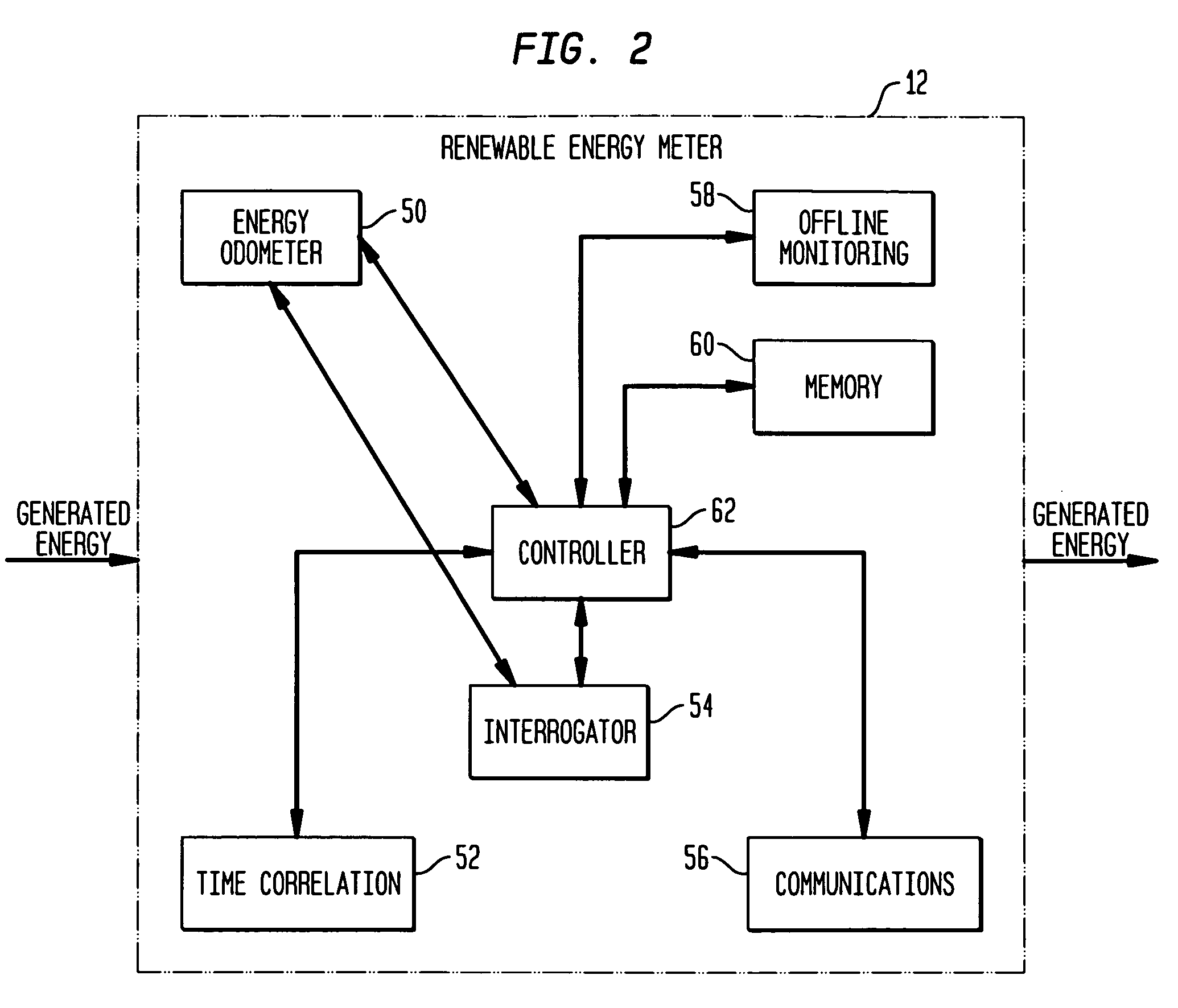
[0024]It is to be understood that each of the components in the meters 12, 14, the monitor 16 and the server 18 which is described below as performing data processing operations is a software module or, alternatively, a hardware module or a combined hardware / software module. In addition, each of the data processing modules in the meters...


PUM


Abstract

Generation of renewable energy for, exportation of the renewable energy from, importation of utility generated energy to, and consumption of energy at, a facility are monitored in substantially real time to provide for substantially real time management and reporting of energy performance of the facility. Monitoring of environmental conditions and facility operations of the facility, also in substantially real time and time correlated with the energy monitoring, is performed to further enhance the management and reporting of the energy performance of the facility.

Description

CROSS REFERENCE TO RELATED APPLICATION[0001]This application claims the benefit of the filing date of U.S. Provisional Patent Application No. 60 / 922,637 filed Apr. 9, 2007, the disclosure of which is hereby incorporated herein by reference.BACKGROUND OF THE INVENTION[0002]Energy usage in facilities, such as buildings, is a large expense. In a campus environment including many buildings, energy usage can cost millions of dollars per year. Managing these costs so that energy costs are minimized while maintaining acceptable performance is a challenge.[0003]Computerized energy management systems (“EMSs”) that can provide for monitoring and managing energy usage in various types of facilities are known. In typical EMSs, a user, such as an operator, uses a mouse or keyboard to navigate various screens displayed on a computer monitor, and to select various displayed options and actions. An EMS generally provides detailed information but no context or meaning, and requires specialized train...

Claims


Application Information

Patent Timeline
Patent Type & Authority Patents(United States)
IPC IPC(8): G01R21/00
CPCG01D4/00G06Q50/06H02J13/001H02J3/382G01R22/10Y02E40/72Y02B70/3216Y04S10/40Y04S20/221Y02B70/346Y04S10/123Y04S20/46Y04S20/525Y04S10/30Y02E60/74H02J3/383H02J3/386Y02E10/563Y02E10/763H02J13/00001H02J13/00002H02J2300/28H02J2300/20H02J2300/24H02J3/381H02J13/00017Y02B70/30Y02B70/34Y02E10/56Y02E10/76Y02E40/70Y02E60/00Y04S20/30Y04S40/124Y04S20/222Y02B70/3225Y02B90/20
Inventor BRZEZOWSKI, EDWARD H.GRABOWSKI, JOSEPH G.
Owner NOVEDA TECH
Why Eureka
Try Eureka