

Transmission synchronizing system, in particular, in the form of a servo synchronizing system
a synchronizing system and transmission technology, applied in the direction of toothed gearings, belts/chains/gearings, mechanical instruments, etc., can solve the problems of reducing the number of ring gears within the synchronizing system, and reducing the number of ring gears
- Summary
- Abstract
- Description
- Claims
- Application Information
AI Technical Summary
Benefits of technology
Problems solved by technology
Method used
Image

Examples
Embodiment Construction
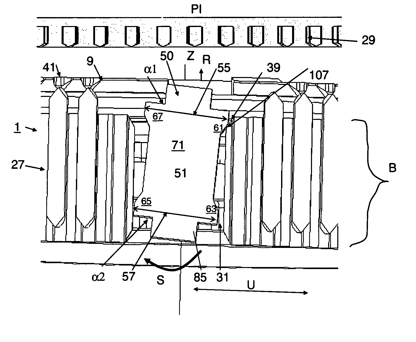
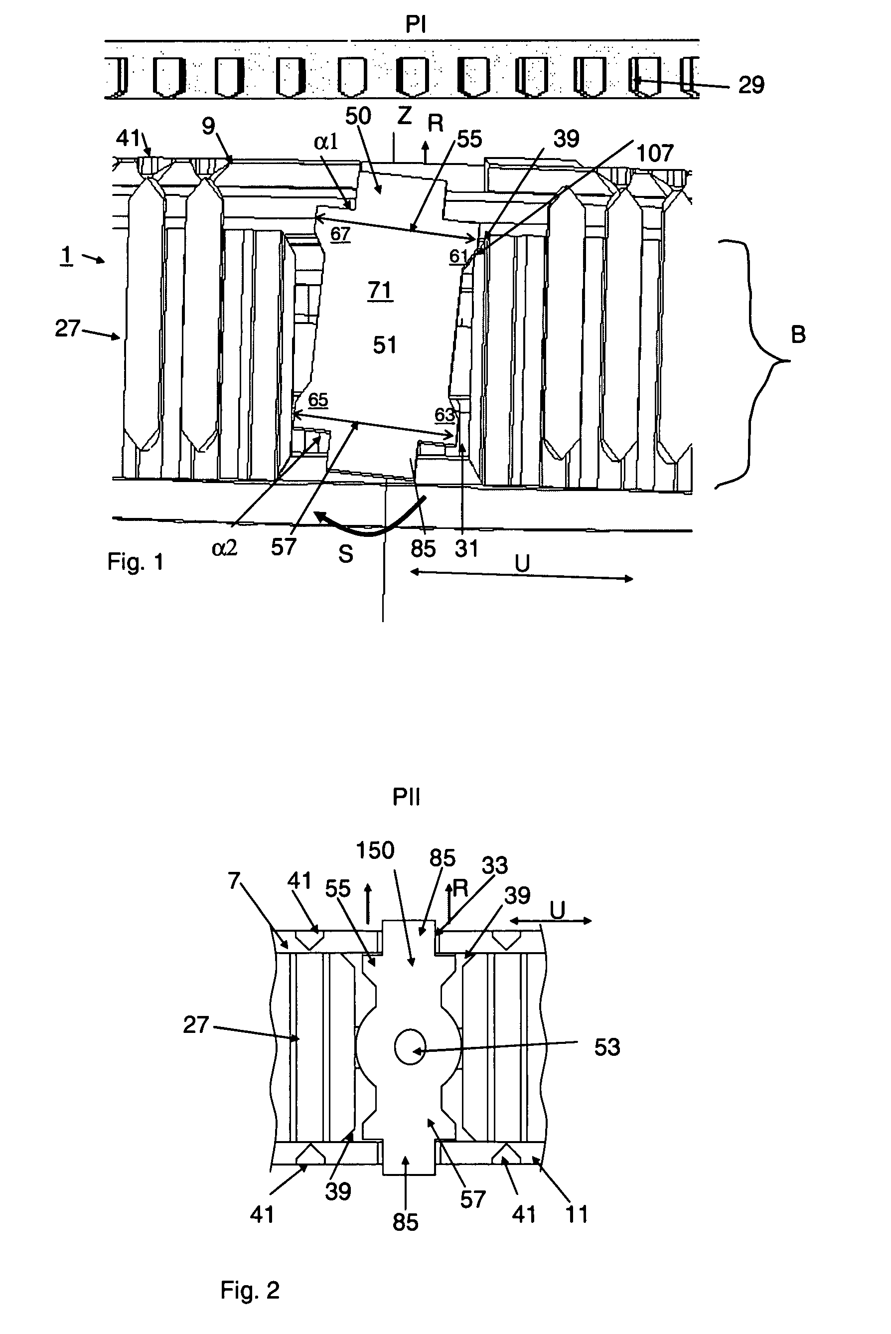
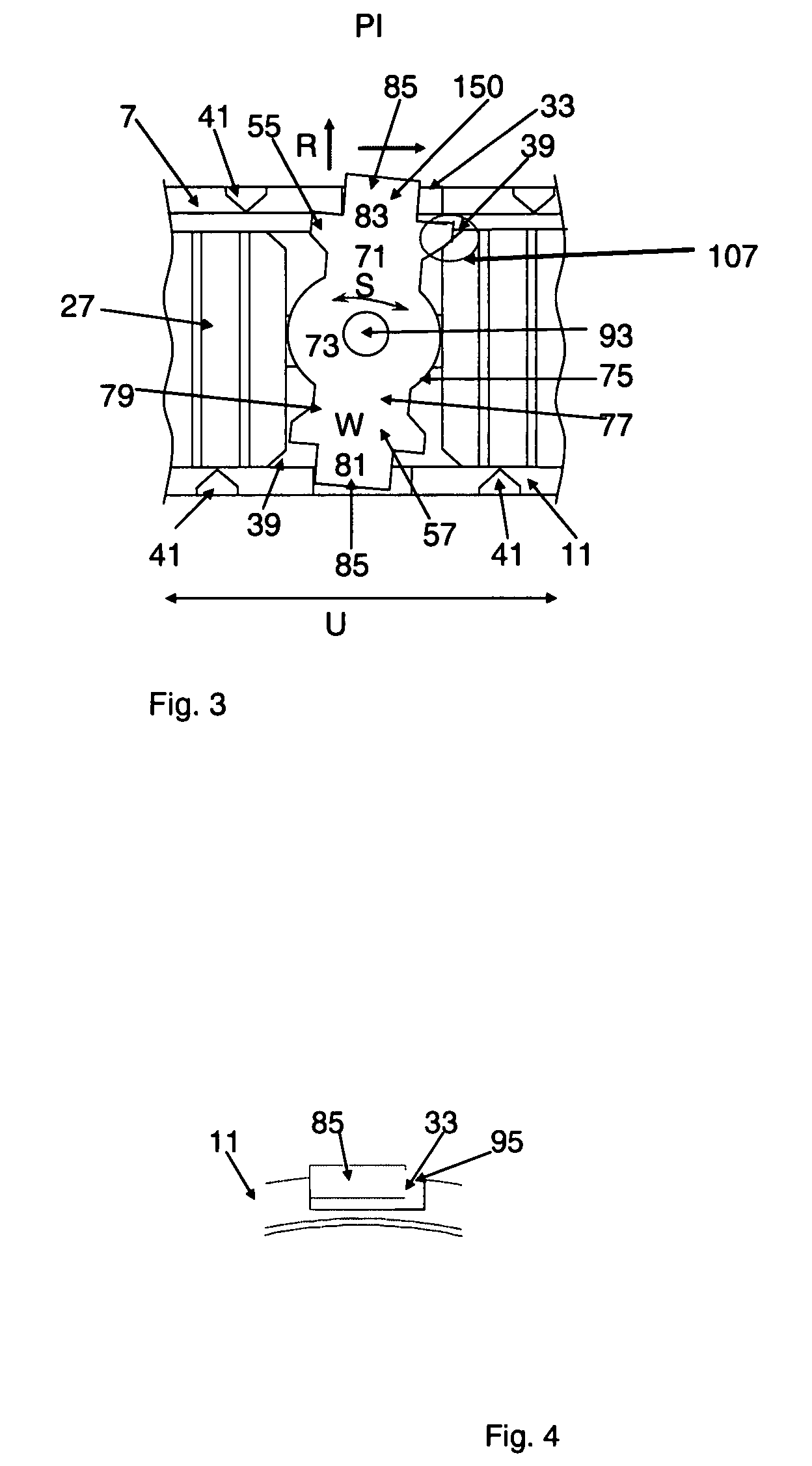
[0067]FIG. 1 shows a pressure piece 50 according to the invention in swivel motion in the synchronizer hub 27, the individual contours of the pressure piece having been reduced to such an extent that particularly notable regions 61, 63, 65, 67 and 55, 57 can become apparent. As is known, a transmission synchronization system 1 according to a usual design is constructed with an idler gear 29, a first outer synchronization ring 9 having an appropriate number of stop teeth 41, and with a shaft 31. The synchronization unit 1 in this case ensures that synchronous operation is achieved between the idler gear 29 and the shaft 31 following synchronizing-in. The synchronization operation is effected with the aid of a pressure piece 50. The pressure piece 50, of which there may also be several over the circumference in the direction of rotation U of the synchronization unit of a transmission synchronization system 1, is located in a recess 39 of the synchronizer hub 27 in such a way that it c...
PUM
 Abstract
Description
Claims
Application Information