Transmission synchronizing system, in particular, in the form of a servo synchronizing system

a synchronizing system and transmission technology, applied in the direction of toothed gearings, belts/chains/gearings, mechanical instruments, etc., can solve the problems of reducing the number of ring gears within the synchronizing system, and reducing the number of ring gears

Inactive Publication Date: 2008-03-20
HOFER PDC
View PDF9 Cites 17 Cited by
  • Summary
  • Abstract
  • Description
  • Claims
  • Application Information

AI Technical Summary

Benefits of technology

[0017]In the case of one design, the I shape of the synchronization pressure piece is achieved through a middle, longitudinal type region, which is delimited by hammer type transverse segments projecting over the middle region. In its length from one transverse segment to the other, the pressure piece is designed so that it can extend over the width of a hub of the transmission shaft. The transverse segments extend at a virtually right angle, preferably a 90° angle, relative to the middle portion. The I-shaped pressure piece is flat overall. The middle, overall longer, region is much narrower than the transverse segments. In the case of exemplary designs, division ratios of 1:1.2 or even 1:2 or even 1:2.5 may be selected as advantageous ratios between the width of the middle, waisted region and the transverse segments extending in the same direction. The shape of the pressure piece favors ease of production as compared with known pressure pieces, e.g., in the case of many designs, it is possible to dispense with a subsequent case-hardening of the bearing and contact parts of the pressure piece. The shape also reduces the requirements in respect of wear.
[0031]The radial groove in the sliding sleeve is shaped, in respect of its taper angle, in such a way that, in the synchronization phase from the blocking to the unblocking by the pressure piece, occurring between the synchronizer ring and the sliding sleeve, an end of the central pin comes into bearing contact and transmits force. In respect of its geometry or its surface bevel, the lateral surface on the synchronization pressure piece is designed to match the course of the recess of the outer synchronization ring. The bevel is preferably one that faces downwards through an angle out of the surface of the synchronization pressure piece or out of the top of the synchronization pressure piece, towards the shaft. This design reduces the frictional action between the pressure piece and the outer synchronization ring at the contact surface, in order to facilitate unblocking. The unblocking motion, which may be a radial motion, is affected favorably by the mounting of the pressure piece during the unblocking phase.
[0033]The pressure piece may be mounted, separately from its base, on a resilient element. The element may be a detent mounting. The arrangement with a resilient, compressible, elastic element provides for a slight raising motion of the pressure piece during insertion into the sliding sleeve groove. A resilient element may be a spring, in particular a spiral or compression spring, guided in the direction of loading in a piston-type opening which encloses it. The guidance effects height stabilization of the spring. The base may additionally be mounted in such a way that it can execute a displacing longitudinal motion in the driving direction. The further degrees of motional freedom of the pressure piece with secure guidance help to improve the equalizing motion of the pressure piece during the synchronizing operation.
[0034]Particular features of the synchronization method according to the full-synchronization principle, preferably with components according to the invention, are the advantageous utilization of the torque, both for reducing the necessary blocking moment and for reducing the unblocking force required. The design shape of the pressure piece and of its mounting and contact points makes it possible to set the blocking security of the pressure piece. In the case of a full synchronization system, an embodiment according to the invention has at least one groove, preferably three or five grooves, a pressure piece or, also, a plurality of pressure pieces, and a shaft hub with a corresponding number of recesses for the individual pressure pieces. If, for example, an I-shaped pressure piece is guided centrally with an engagement in the groove, the unblocking force and the synchronization force can be reduced in equal measure, as compared with pressure pieces without servo synchronization. There is to be no unblocking before equality of rotational speed is attained. The design setting of parameters, resulting from the shape and structure of the surface, allows a blocking security of greater than 1 to be set.
[0036]The shift force necessary for synchronizing can be reduced with the use of a synchronization pressure piece, according to the invention, that has a double hammer shape with projecting stems, also described as in I shape with lugs, the pressure piece being mounted so as to be capable of swivel motion about a central mounting point, and being in engagement, depending on the respective swivel position, both with a recess in the hub and at a bevel in the groove of the sliding sleeve. As a result, the number of synchronization cones can be reduced, in particular in the lower gears. The invention departs from the widely observed tendency to realize the necessary shift forces through the use of more and more synchronization cones. Instead of having to use two or three synchronization cones for a first or second gear of a manual shift transmission of a motor vehicle, a synchronization unit according to the invention, having a full-servo pressure piece, can manage with only one cone. A light, easily produced pressure piece such as, for example, a multiply formed sheet metal piece, is advantageous. The geometries and the angles are used to set the servo action, the necessary shift force and the torque to be utilized. The blocking security, the amplification factor and the self-locking security are set as required through the geometric portions selected on the synchronization pressure piece and at the transitions between the synchronization pressure piece and the components bearing on or in contact with it. It is thus possible to select a geometric pairing which increases the blocking security in the same measure as the servo amplification factor.
[0038]Embodiments of the invention thus serve to increase the gear-shifting performance during synchronization, while the parts to be used are easily produced and integrated. For example, the number of ring gears within the synchronizing system has been reduced. In addition, large torques can be transmitted with less force by means of a synchronization system according to the invention, with less cogging occurring in the transmission.

Problems solved by technology

This means that the resource requirement for modification is limited in the case of introduction of an H pressure piece, and customer clearance is more easily obtainable.
A disadvantage is the necessity of a repeat, separate hardening of the ends of the H piece during production.

Method used


Image

  • Transmission synchronizing system, in particular, in the form of a servo synchronizing system
  • Transmission synchronizing system, in particular, in the form of a servo synchronizing system
  • Transmission synchronizing system, in particular, in the form of a servo synchronizing system

Examples


Embodiment Construction

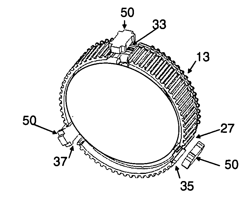
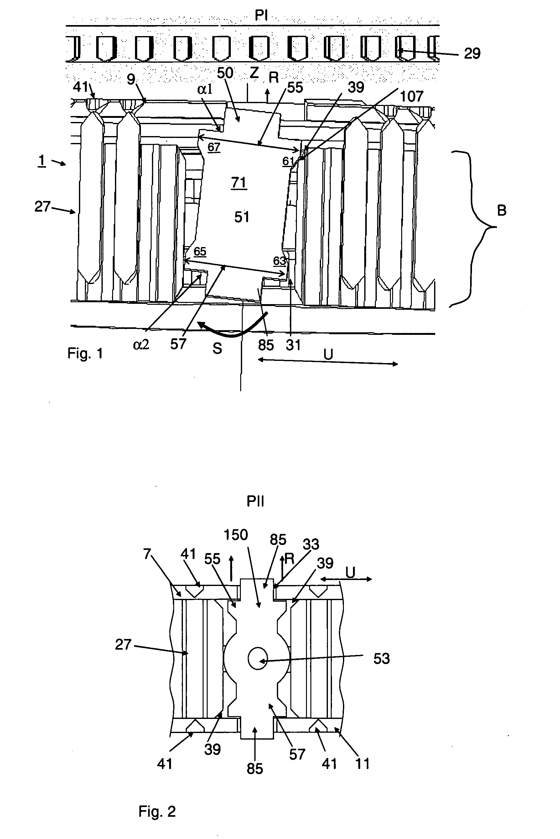
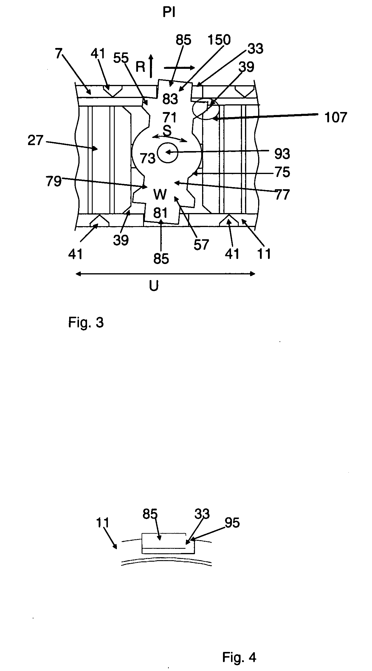
[0067]FIG. 1 shows a pressure piece 50 according to the invention in swivel motion in the synchronizer hub 27, the individual contours of the pressure piece having been reduced to such an extent that particularly notable regions 61, 63, 65, 67 and 55, 57 can become apparent. As is known, a transmission synchronization system 1 according to a usual design is constructed with an idler gear 29, a first outer synchronization ring 9 having an appropriate number of stop teeth 41, and with a shaft 31. The synchronization unit 1 in this case ensures that synchronous operation is achieved between the idler gear 29 and the shaft 31 following synchronizing-in. The synchronization operation is effected with the aid of a pressure piece 50. The pressure piece 50, of which there may also be several over the circumference in the direction of rotation U of the synchronization unit of a transmission synchronization system 1, is located in a recess 39 of the synchronizer hub 27 in such a way that it c...


PUM


Abstract

The invention relates to a synchronization piece which, as part of a servo synchronization system comprising a sliding sleeve, a clutch body, a synchronizer ring and an idler gear, can synchronize a transmission having toothed wheel gears. The invention furthermore relates to an entire synchronizing system having a synchronization piece according to the invention. A full-servo synchronization system is also presented.

Description

PRIORITY CLAIM[0001]This application claims the benefit of German patent application DE 10 2006 044 352.7, titled “Getribesynchronisierung, insbesondere in der Form einer Servo-Synchronisierung,” which was filed Sep. 18, 2006, the disclosure of which application is incorporated herein in its entirety by this reference.FIELD OF THE INVENTION[0002]The invention relates to a synchronization piece which, as part of a servo synchronization system comprising a sliding sleeve, a clutch body, a synchronizer ring and an idler gear, can synchronize a transmission having toothed wheel gears. The invention furthermore relates to an entire synchronizing system having a synchronization piece according to the invention. A full-servo synchronization system is also presented.BACKGROUND[0003]In the parlance of the transmission designer, a synchronization piece is also termed a pressure piece or synchronization pressure piece.[0004]As presented in detail at the VDI conference “Getriebe in Fahrzeugen 2...

Claims


Application Information

Patent Timeline
Patent Type & Authority Applications(United States)
IPC IPC(8): F16H3/38
CPCF16D23/06F16D2023/0618Y10T74/19284F16D2023/0656F16D2023/065
Inventor HACKL, THOMASBERGER, MARTINKALMBACH, KLAUSSTEINZ, JANINA
Owner HOFER PDC
Why Eureka
Try Eureka