Projection image display apparatus having a noise removal filter portion

a technology of noise removal filter and projection image, which is applied in the direction of color television details, television systems, instruments, etc., can solve the problems of increased noise, deterioration of cooling capability, and increased output apparatus requirements, so as to reduce costs

Active Publication Date: 2012-01-31
SANYO TECH CENT SHENZHEN +1
View PDF5 Cites 29 Cited by
  • Summary
  • Abstract
  • Description
  • Claims
  • Application Information

AI Technical Summary

Benefits of technology

[0008]The present invention has been made in order to solve the disadvantage as described above. It is an objective of the invention to provide a projection type image display apparatus that includes a power source unit light that can realize, even when a light source lamp has a higher output, reduced noise enabled by an improved cooling capability and a reduction in cost enabled by an EMC measure and the like.
[0010]According to this configuration, the noise removal filter portion is separated from the body of the power source unit and the separated noise removal filter portion is provided in the vicinity of the side wall of the housing on which the power source inlet is provided, and of the body of the power source unit, respectively. This configuration can downsize the body of the power source unit even when the light source lamp has a higher output. Thus, reduced noise enabled by the improved cooling capability can be achieved and the connecting wire can be the minimum length to provide reduced cost enabled by an efficient EMC measure (e.g., reduced use of a core).
[0012]By the above configuration, the side wall of the housing is free from a power source code. Thus, the effect of the above-described reduced cost can be obtained without deteriorating the usability of the side face of the housing.
[0014]By the structure as described above, the connecting wire can have the minimum length even when the noise removal filter portion is provided along the side wall of the back face. Thus, the effect of the above-described reduced cost can be obtained without causing a complicated arrangement of the respective components in the housing.

Problems solved by technology

However, the larger output the apparatus requires, the larger the power source unit becomes, because the power source unit requires a noise removal filter portion having a core (coil) that cannot be downsized.
A power source unit having a larger size causes a fan for cooling this power source unit to have a larger size or a higher output (rotating speed), resulting in a deteriorated cooling capability and increased noise.
However, this arrangement is disadvantageous in that noise easily enters a connecting wire to cause an increased use of a core, which raises a difficult problem of an Electro Magnetic Compatibility (EMC) measure, thereby causing a higher cost.

Method used


Image

  • Projection image display apparatus having a noise removal filter portion
  • Projection image display apparatus having a noise removal filter portion
  • Projection image display apparatus having a noise removal filter portion

Examples


Embodiment Construction

[0032]One embodiment of the present invention will now be described below in detail with reference to the drawings.

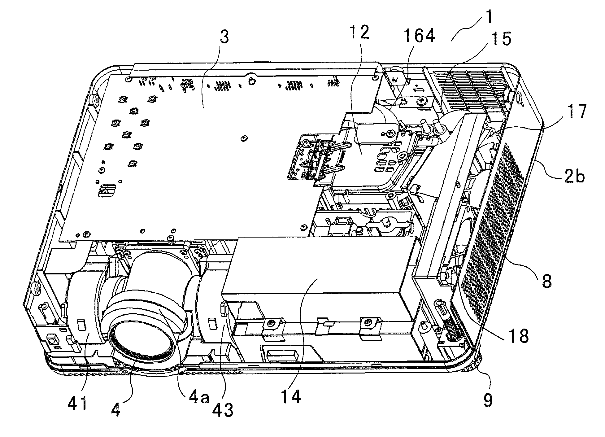
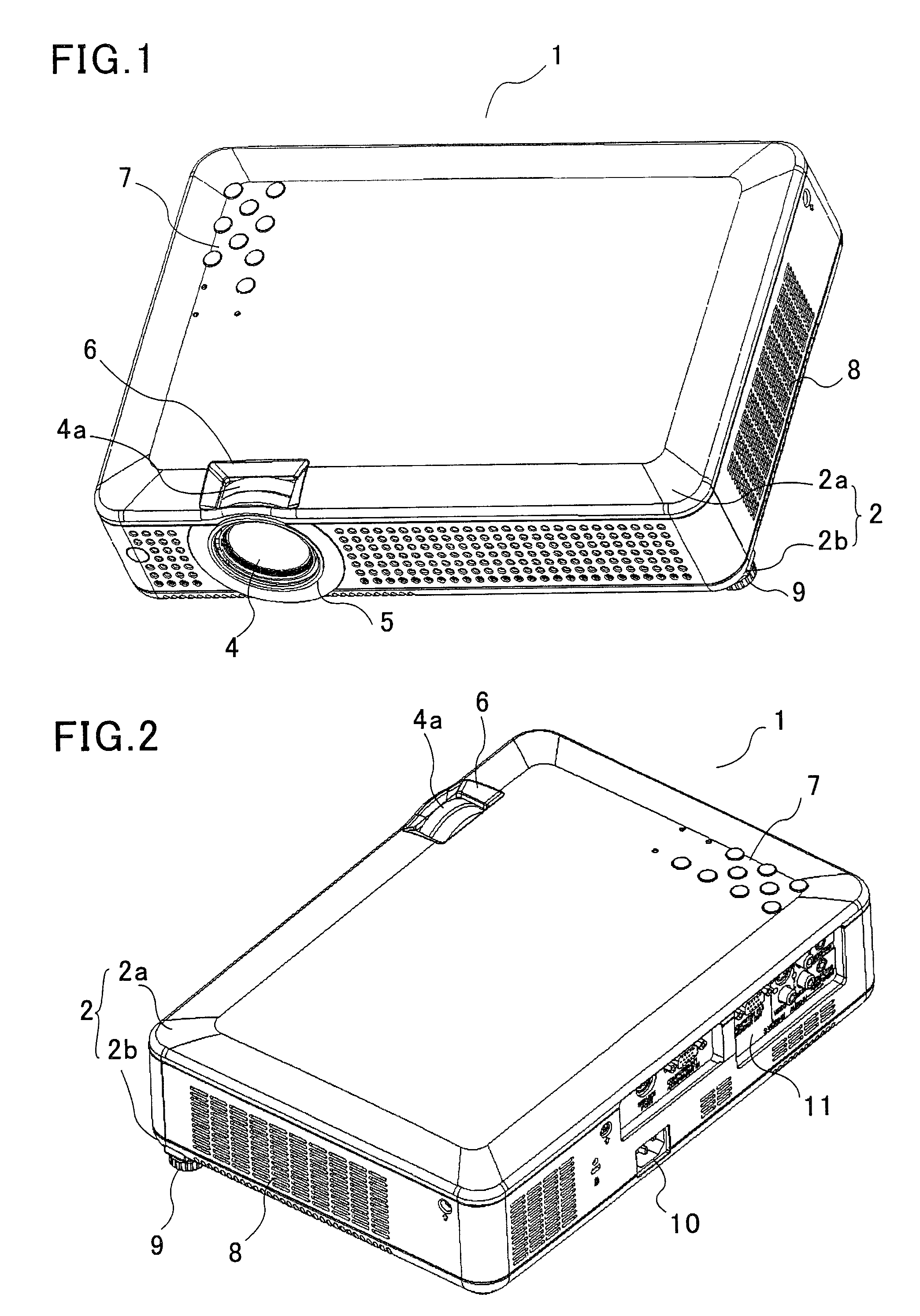
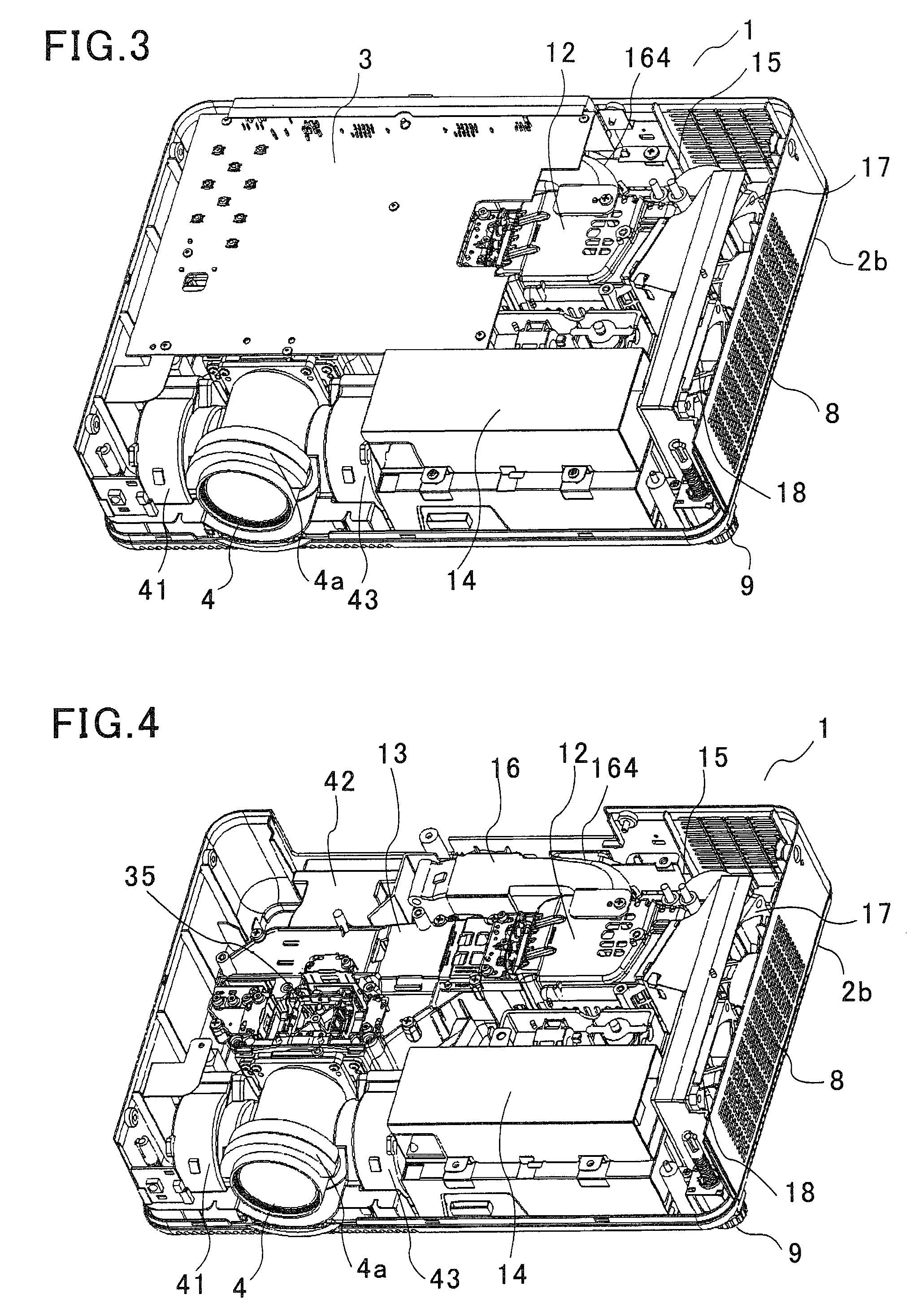
[0033]FIG. 1 is a perspective view of a liquid crystal projector as one embodiment of a projection type image display apparatus according to the present invention seen obliquely from above from the front side, FIG. 2 is similarly a perspective view seen obliquely from above from the back side, FIG. 3 is a perspective view in which the upper case in FIG. 1 is removed, FIG. 4 is a perspective view in which a main control substrate is further removed, FIG. 5 is a perspective view in which an optical system is further removed, and FIG. 6 is a top plan view of FIG. 5.

[0034]As shown in FIGS. 1 and 2, a housing 2 forming an outer hull of this liquid crystal projector 1 is compact, has a horizontally long thin rectangular shape, and consists of an upper case 2a and a lower case 2b. When the upper case 2a and a main control substrate 3 are removed, the interior thereof is displa...


PUM


Abstract

In a projection image display apparatus, a noise removal filter portion 15 is separated from a power source unit body 14. The separated noise removal filter portion 15 is provided in the vicinity of a side wall of a housing on which a power source inlet is provided, and of the power source unit body 14, respectively. Specifically, the power source unit body 14 is provided along a side wall of a front face of the horizontally-long housing of the projection image display apparatus and the noise removal filter portion 15 is provided in a position opposed to the power source unit body 14 in a side wall of the back face. As a result, even when a light source lamp has a higher output, the projection image display apparatus can achieve reduced noise by an improved cooling capability and reduced cost enabled by an efficient Electro Magnetic Compatibility (EMC) measure and the like.

Description

FIELD OF THE INVENTION[0001]The present invention relates to a projection type image display apparatus that has a noise removal filter portion for removing noise coming via a power source inlet and that includes a power source unit for supplying power to the respective parts including a light source lamp stored in a housing.BACKGROUND OF THE INVENTION[0002]A projection type image display apparatus such as a liquid crystal projector uses, as a light source lamp, a high-pressure mercury lamp, metal halide lamp, and the like that are driven with a high voltage to emit light with high intensity. Thus, this projection type image display apparatus includes a power source unit that includes a power source circuit substrate including circuit components for supplying power to the respective parts of the apparatus and a ballast circuit substrate having thereon circuit components for supplying power exclusive to a light source lamp. This power source unit includes a noise removal filter portio...

Claims


Application Information

Patent Timeline
Patent Type & Authority Patents(United States)
IPC IPC(8): G03B21/14G03B21/22H04N5/217
CPCG03B21/14G03B21/22G03B21/16G03B21/145
Inventor MAO, XIAOLINYAN, YANYUNLIANG, XIANGDONGKONG, XIANGFEIWANG, YUNZHENG, WANJUNGUAN, YIHUANG, YANSHANSARUWATARI, TOSHIHIROOKAZAKI, SHOJIRENBUTSU, TADASHI
Owner SANYO TECH CENT SHENZHEN
Why Eureka
Try Eureka