
Systems and methods for calibration of gyroscopes and a magnetic compass

a technology of magnetic compass and gyroscope, which is applied in the field of systems and methods for calibration of gyroscopes and magnetic compass, can solve the problems of introducing errors into the magnetic compass bearing readings, degrading and affecting the accuracy of the magnetic compass

Inactive Publication Date: 2012-01-31
HONEYWELL INT INC
View PDF27 Cites 30 Cited by
  • Summary
  • Abstract
  • Description
  • Claims
  • Application Information

AI Technical Summary

Benefits of technology

The patent describes a way to calibrate a compass and gyroscopes in the field at the same time. This is done by rotating the calibration system and using the data from the compass and gyroscopes to determine compensation for both components. The technical effect is that it allows for more accurate and reliable navigation in the field without the need for a separate calibration process for each component.

Problems solved by technology

However, when the magnetic compass is deployed in the field, the accuracy of the magnetic compass may be degraded.
Thus, if the magnetic compass is calibrated prior to installation in a device and / or deployment in the field, the magnetic fields altered by the nearby metals or the other magnetic materials may introduce error into the magnetic compass bearing readings.
Accordingly, moving the magnetic compass into the vicinity of external metals or other magnetic materials may introduce error into the magnetic compass bearing readings.
Gyroscope may also be inaccurate during use in the field.
For example, gyroscopes are subject to drift rates.

Method used


Image

  • Systems and methods for calibration of gyroscopes and a magnetic compass
  • Systems and methods for calibration of gyroscopes and a magnetic compass
  • Systems and methods for calibration of gyroscopes and a magnetic compass

Examples


Embodiment Construction

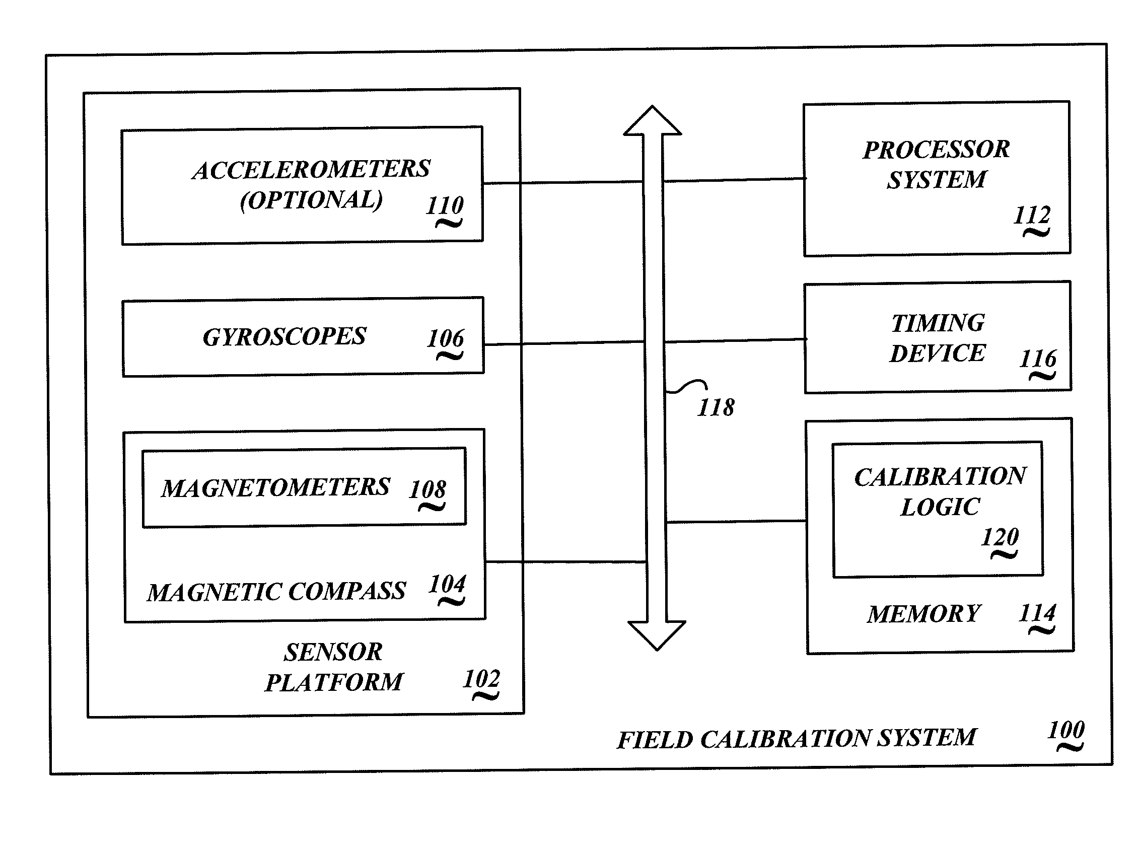
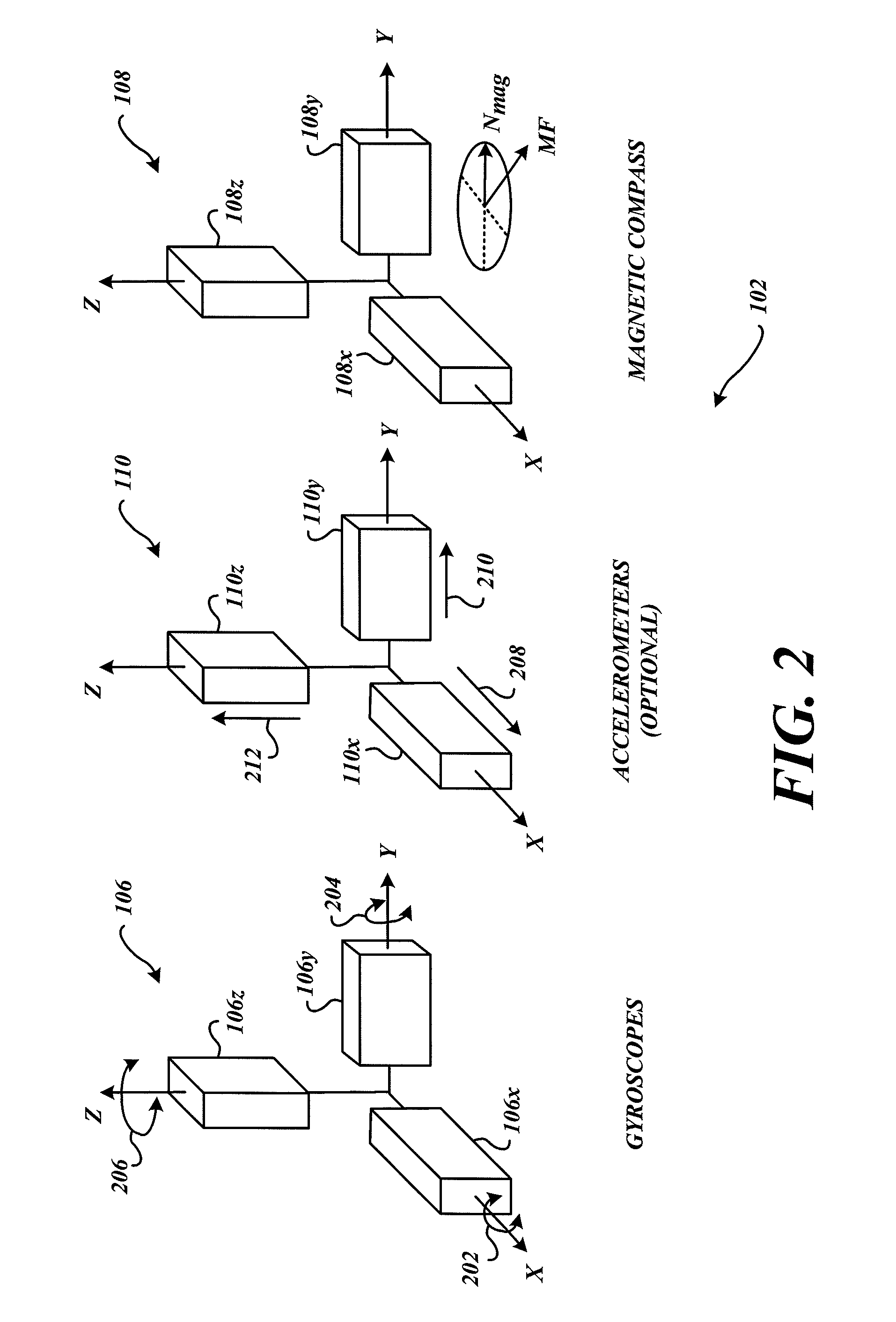
[0012]FIG. 1 is a block diagram of an embodiment of a field calibration system 100. An exemplary embodiment of the field calibration system 100 includes a sensor platform 102 with a magnetic compass 104 and a plurality of gyroscopes 106 thereon. An exemplary magnetic compass 104 may include one or more magnetometers 108. Further, an optional plurality of accelerometers 110 may be included on the sensor platform 102.

[0013]During calibration, the sensor platform 102 is rotated in three dimensional space, referred to herein interchangeably as a calibration rotation. Preferably, the sensor platform 102 is rotated at least 360°. The x-y plane of the sensor platform 102 may be oriented in a horizontal position or a tilt position during the calibration rotation.

[0014]The field calibration begins by rotating the field calibration system 100. Based upon the rotation sensed by the magnetic compass 104 and the gyroscopes 106, the field calibration system 100 determines compensation for both th...


PUM


Abstract

Calibration systems and methods simultaneously calibrate a magnetic compass and gyroscopes. An exemplary embodiment rotates the field calibration system. Based upon the rotation sensed by the magnetic compass and the gyroscopes, the field calibration system determines compensation for both the magnetic compass and the gyroscopes.

Description

BACKGROUND OF THE INVENTION[0001]Magnetic compasses are employed in a variety of position and / or orientation sensing systems. One or more magnetometers may be used in the compass. Calibration of the magnetic compass is relatively straightforward in a controlled test environment where a calibration rotation can be precisely controlled. However, when the magnetic compass is deployed in the field, the accuracy of the magnetic compass may be degraded.[0002]The device in which the magnetic compass resides may contain metals or other magnetic materials which alter the magnetic field in the vicinity of the magnetic compass. For example, the magnetic compass may be installed in a vehicle, such as an aircraft, ship, or military tank. Thus, if the magnetic compass is calibrated prior to installation in a device and / or deployment in the field, the magnetic fields altered by the nearby metals or the other magnetic materials may introduce error into the magnetic compass bearing readings.[0003]If...

Claims


Application Information

Patent Timeline
Patent Type & Authority Patents(United States)
IPC IPC(8): G06F19/00
CPCG01C17/38
Inventor JUDD, TOM
Owner HONEYWELL INT INC
Learn More