
Data eye monitor method and apparatus

a data eye monitor and data eye technology, applied in the field of computer systems with ddr sdram memory, can solve problems such as difficulty in extracting data from the interface, and achieve the effect of improving data eye centering

Inactive Publication Date: 2012-01-31
INT BUSINESS MASCH CORP
View PDF115 Cites 4 Cited by
  • Summary
  • Abstract
  • Description
  • Claims
  • Application Information

AI Technical Summary

Benefits of technology

This method provides an infinite persistent data eye, enabling continuous monitoring and adjustment of the memory interface, improving data eye centering and ensuring accurate latching of data signals throughout the operation, even at higher memory interface speeds.

Problems solved by technology

With the advent of high speed external memories that employ a source synchronous interface it has become difficult to extract data from the interface.

Method used


Image

  • Data eye monitor method and apparatus
  • Data eye monitor method and apparatus
  • Data eye monitor method and apparatus

Examples


Embodiment Construction

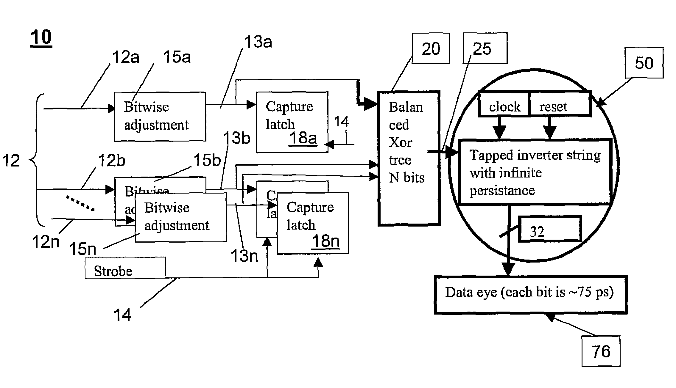
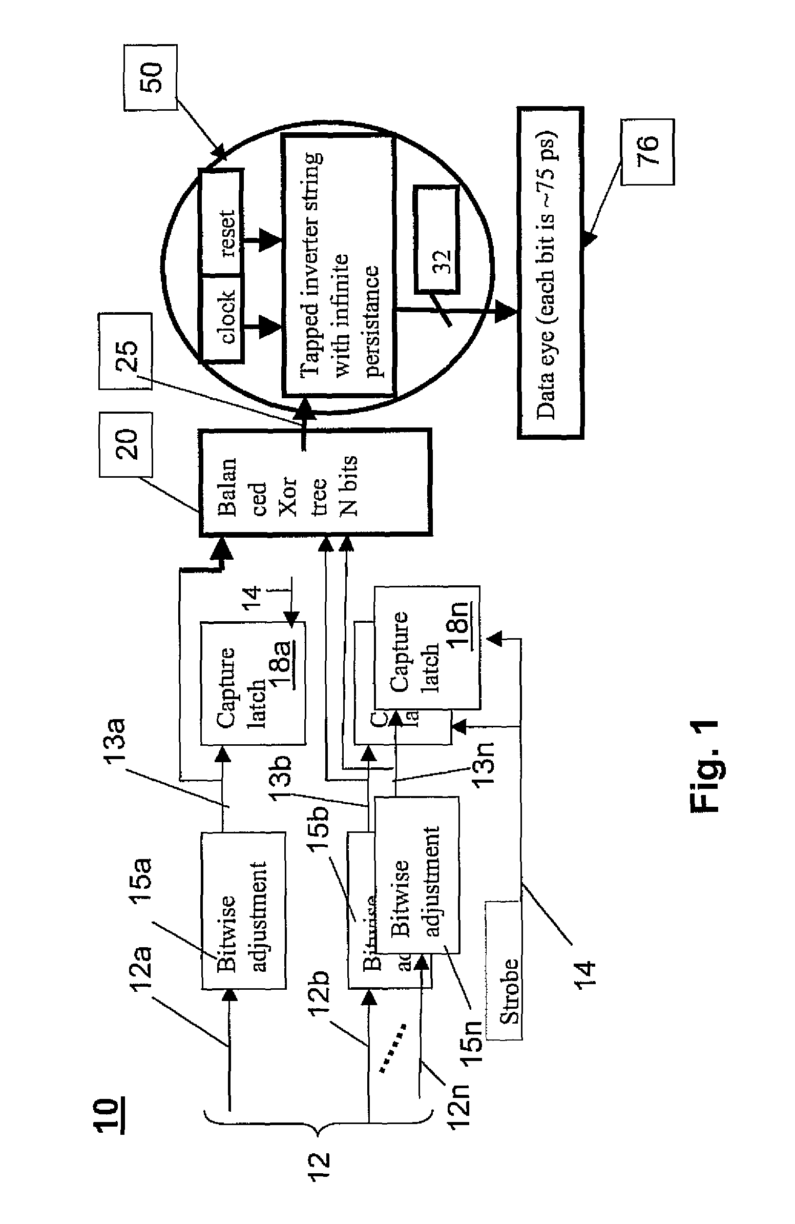
[0039]FIG. 1 depicts generally an overall base architecture 10 of a DDR Data eye monitor apparatus 10 of the present invention. The DDR is advantageously employed at the data path of any digital circuit, where the digital circuit captures data signals 12 using a strobe signal 14. As known, in a typical use of a SDR DRAM, the data bits are associated with a strobe line which functions as a clock for the data bits when they are captured into the receiving circuit (e.g., integrated circuit) chip. As will be explained, the data eye monitor and methodology of the present invention provides a “persistent” data eye that can be used to adjust the input data strobe signal 14 to ensure accurate latching of the data signals at the input of a receiving data latch circuit throughout its operation.

[0040]As shown in FIG. 1, the DDR Data eye monitor apparatus 10 comprises a plurality of bit adjuster elements 15a, . . . , 15n, each bit adjuster element corresponding with a respective synchronous dat...


PUM

PropertyMeasurementUnit
timeaaaaaaaaaa
time shiftaaaaaaaaaa
speedsaaaaaaaaaa

Abstract

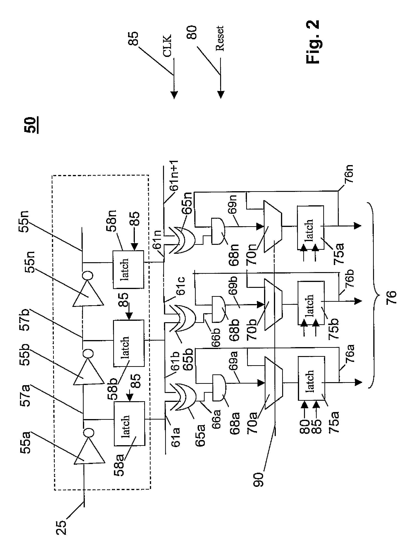
An apparatus and method for providing a data eye monitor. The data eye monitor apparatus utilizes an inverter / latch string circuit and a set of latches to save the data eye for providing an infinite persistent data eye. In operation, incoming read data signals are adjusted in the first stage individually and latched to provide the read data to the requesting unit. The data is also simultaneously fed into a balanced XOR tree to combine the transitions of all incoming read data signals into a single signal. This signal is passed along a delay chain and tapped at constant intervals. The tap points are fed into latches, capturing the transitions at a delay element interval resolution. Using XORs, differences between adjacent taps and therefore transitions are detected. The eye is defined by segments that show no transitions over a series of samples. The eye size and position can be used to readjust the delay of incoming signals and / or to control environment parameters like voltage, clock speed and temperature.

Description

STATEMENT REGARDING FEDERALLY SPONSORED RESEARCH OF DEVELOPMENT[0001]The U.S. Government has a paid-up license in this invention and the right in limited circumstances to require the patent owner to license others on reasonable terms as provided for by the terms of Contract. No. B554331 awarded by the Department of Energy.CROSS-REFERENCE TO RELATED APPLICATIONS[0002]The present invention is related to the following commonly-owned, co-pending United States patent applications filed on even date herewith, the entire contents and disclosure of each of which is expressly incorporated by reference herein as if fully set forth herein. U.S. patent application Ser. No. 11 / 768,777, for “A SHARED PERFORMANCE MONITOR IN A MULTIPROCESSOR SYSTEM”; U.S. patent application Ser. No. 11 / 768,645, for “OPTIMIZED COLLECTIVES USING A DMA ON A PARALLEL COMPUTER”; U.S. patent application Ser. No. 11 / 768,781, for “DMA SHARED BYTE COUNTERS IN A PARALLEL COMPUTER”; U.S. patent application Ser. No. 11 / 768,784...

Claims


Application Information

Patent Timeline
Patent Type & Authority Patents(United States)
IPC IPC(8): G06K5/04G11B5/00G11B20/20
CPCG06F13/1689
Inventor GARA, ALAN G.MARCELLA, JAMES A.OHMACHT, MARTIN
Owner INT BUSINESS MASCH CORP
Learn More