Sampling apparatus

a technology of sampling apparatus and sampling chamber, which is applied in the field of sampling apparatus, can solve the problems of difficult to drain the lighter one (oil), difficult to represent the phases collected by gravity traps, and complex flow regime of multiphase fluid mixture, etc., and achieve the effect of decreasing the volume of the chamber

Active Publication Date: 2012-02-07
SCHLUMBERGER TECH CORP
View PDF8 Cites 2 Cited by
  • Summary
  • Abstract
  • Description
  • Claims
  • Application Information

AI Technical Summary

Benefits of technology

[0013]The sampling apparatus enables to maintain sample at line flowing conditions (pressure and temperature) during the entire sampling process in order to prevent compositional change due to mass transfers.
[0030]a second step comprising the steps of flushing at least one unwanted phase enriched fluid back to the main pipe by coupling the sample chamber to one sampling probe and decreasing the volume of the chamber,
[0032]a third step comprising the step of expelling the fluid enriched in the selected phase out of the chamber by coupling the chamber to the outlet and decreasing the volume of the chamber.

Problems solved by technology

In addition, the multiphase fluid mixture may have complex flow regimes, e.g. mist, bubble, slug, churn flows, etc .
The representation of the phases collected by the gravity traps is questionable because the phases in the gravity traps are not refreshed continuously.
These solids often plug the drain preventing further sampling, and if the heaviest liquid flow (water) is important, it is very difficult to drain the lighter one (oil) as the accumulation rate could be faster than the one draining.
This method does not enable to control the sampled volume of each phase, which could lead to an insufficient quantity of a given phase for the post-sampling measurements.

Method used


Image

  • Sampling apparatus
  • Sampling apparatus
  • Sampling apparatus

Examples


Embodiment Construction

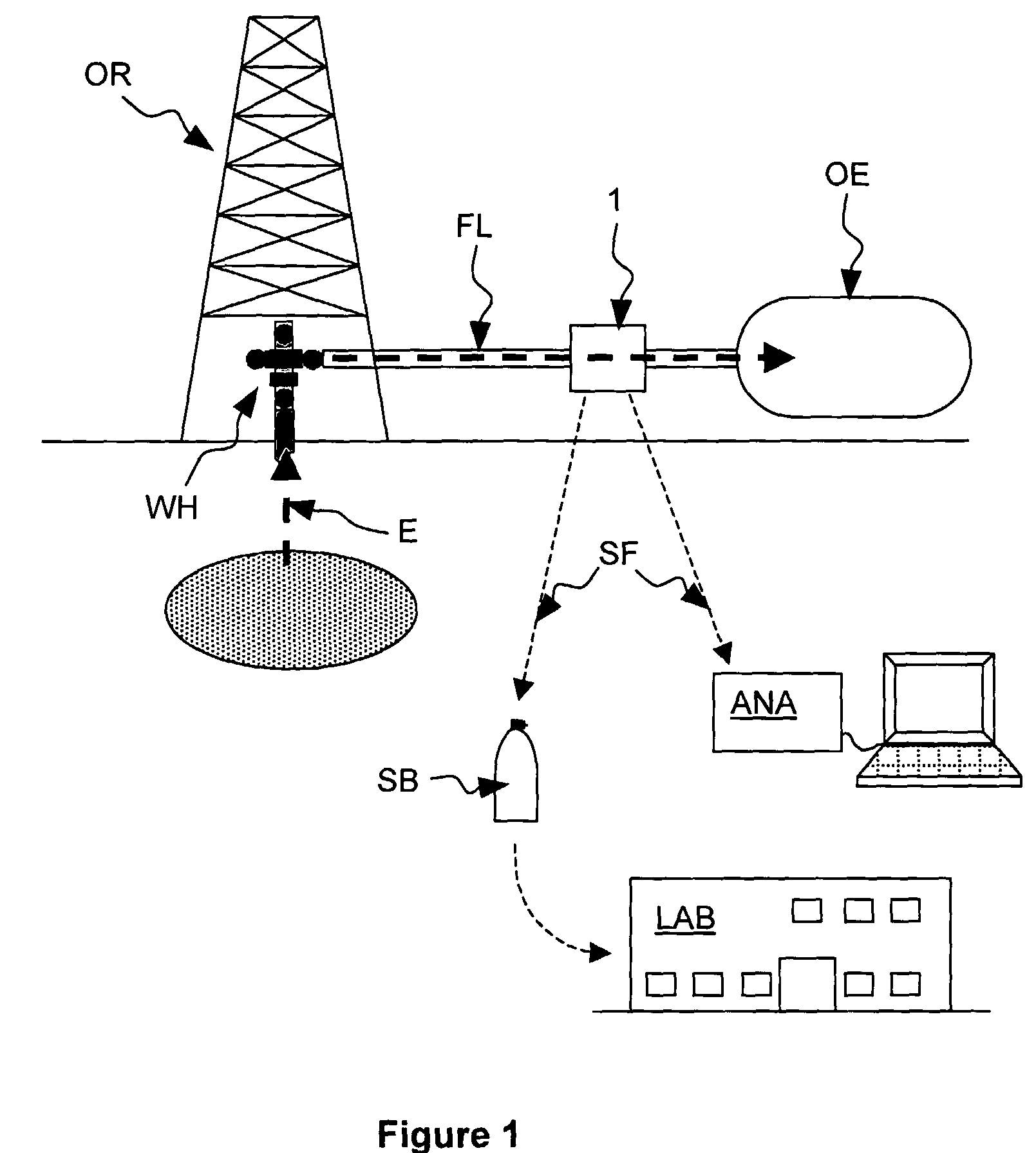
[0037]FIG. 1 shows schematically a hydrocarbon rig OR. An effluent E flows out of the well from a well head WH. The well head WH is connected to various well equipments OE through a main pipe FL. The well equipments may comprise any known well testing or well production equipments that will not be further described. The main pipe FL comprises a sampling apparatus 1 for sampling a fluid enriched in a selected phase from the effluent E constituted by a multiphase fluid mixture. The sampling apparatus provide a sampled fluid SF either to an appropriate analyzer ANA for on-field analysis, or into a sampling bottle SB for subsequent analysis by a laboratory LAB.

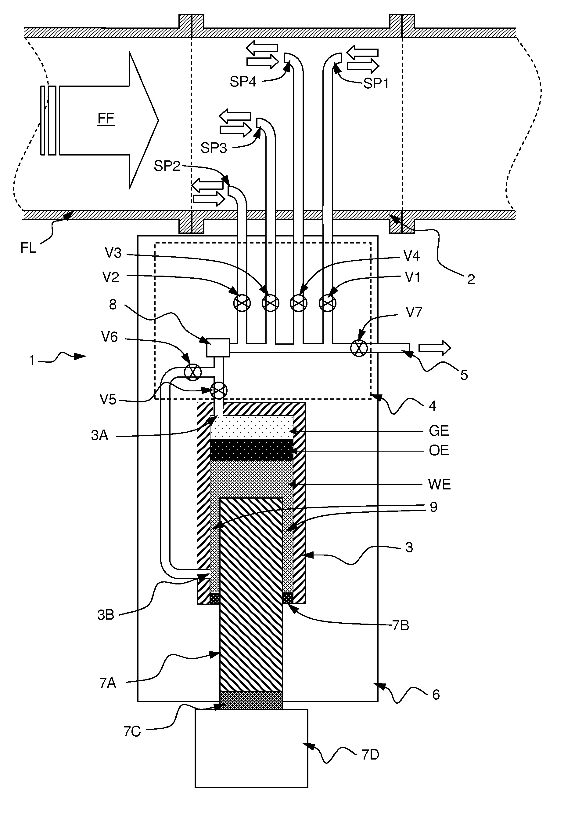
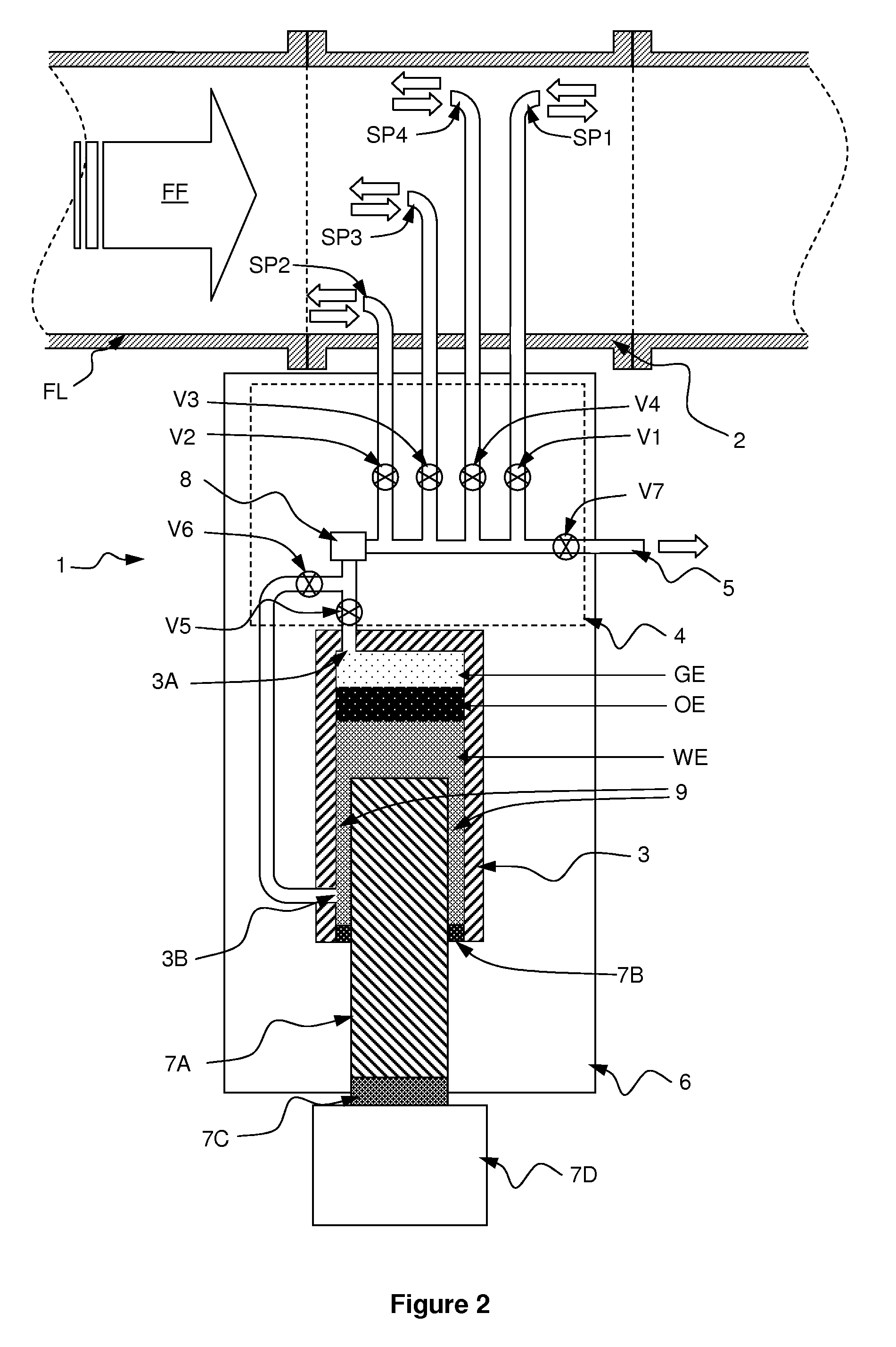
[0038]FIG. 2 schematically illustrates an apparatus for sampling a single phase from a multiphase fluid mixture according to the invention.

[0039]The sampling apparatus 1 comprises a sampling pipe 2, a sample chamber 3 of variable volume, a valve manifold 4 and a temperature controlling arrangement 6.

[0040]The sampling pipe 2 is ad...


PUM

PropertyMeasurementUnit
temperatureaaaaaaaaaa
areaaaaaaaaaaa
volumeaaaaaaaaaa

Abstract

A sampling apparatus for sampling a fluid enriched in a selected phase from a multiphase fluid mixture flowing into a main pipe, the multiphase fluid mixture containing at least the selected phase and one other phase, the apparatus comprising: —a sampling arrangement: for taking a fluid sample of the multiphase fluid mixture flowing into the main pipe, —a sample chamber having a variable volume for collecting the fluid sample of the multiphase fluid mixture and letting settle by gravity the fluid sample into the fluid enriched in the selected phase and at least another phase enriched fluid, and —a valve manifold coupling the sampling arrangement to the sample chamber for driving the fluid sample in the sample chamber and for driving the fluid enriched in the selected phase to a sample outlet and the other phase enriched fluid back to the main pipe.

Description

FIELD OF THE INVENTION[0001]The invention relates to an apparatus for sampling a single phase from a multiphase fluid mixture.[0002]A particular application of the invention relates to the sampling of the various phases of a multiphase fluid mixture from a hydrocarbon well. Such a multiphase fluid mixture typically comprises three phases: an aqueous phase, a liquid hydrocarbon phase and a gaseous hydrocarbon phase.BACKGROUND OF THE INVENTION[0003]After a hydrocarbon well has been drilled and made safe, various operations are generally carried out:[0004]well testing operations (serving to characterize the various components of the effluent flowing out of well, and to estimate the production capacities of the well), and subsequently[0005]well producing operation as long as the oil produced is satisfactory in term of quality, flowing rate, etc . . . .[0006]During these operations, the composition of the effluent varies. The effluent that is initially collected is essentially made up of...

Claims


Application Information

Patent Timeline
Patent Type & Authority Patents(United States)
IPC IPC(8): G01N1/22
CPCG01N1/2035G01F1/74
Inventor GUIEZE, PAULMACWILLIAM, DAVIDKOTZAKOULAKIS, KOSTAS
Owner SCHLUMBERGER TECH CORP
Why Eureka
Try Eureka