
Sheet post-processing apparatus

a post-processing apparatus and sheet technology, applied in electrographic process, instruments, transportation and packaging, etc., can solve the problems of reducing the size of the apparatus, reducing the discharge capacity, and reducing the storage amount of debris, etc.

Active Publication Date: 2012-02-07
COPYER +1
View PDF14 Cites 13 Cited by
  • Summary
  • Abstract
  • Description
  • Claims
  • Application Information

AI Technical Summary

Benefits of technology

[0016]By this means, the sheet post-processing apparatus has a rational arrangement of means (units) for performing various kinds of post-processing, and thereby enables the apparatus size to be drastically reduced as compared with the conventional apparatus. Further, since the first discharge outlet can be situated in a relatively high position, it is possible to use the lower area outside the first discharge outlet as a space for a discharge tray, and to enhance the discharge capacity. Furthermore, since the lower space inside the apparatus frame can be used as a storage space for cutting debris, the storage amount of debris is also increased, and it is possible to reduce the frequency of halting the apparatus and improve the processing efficiency of the entire apparatus.
[0017]Moreover, the branch portion is disposed on the upstream side of the punch means in the carrying direction, in other words, the punch means is disposed in the carrying path between the sheet branch portion, which turns a sheet fed from the carry-in entrance to the center-folding means, and the end binding means, and therefore, the center-folding means can be shifted to the lower side from the lower center in the apparatus. It is thereby possible to effectively use the lower space inside the apparatus frame, and the lower space can be used as a storage section for center-folded sheets.
[0018]Then, since the punch means is disposed on the downstream side of the carrying path, it is possible to install the saddle-stitching center-folding processing means sufficiently close to the sheet carry-in entrance side, such a configuration also enables the cutting means to be situated on the inner side than the second discharge outlet, and the risk is eliminated that an operator receives a wound in the finger and / or hand by the cutting apparatus. Further, it is made possible to maximize the storage capacity of bunches of sheets in a stack tray, and by sharing a plurality of trays as the stack tray and a booklet tray, the effect is produced of dramatically improving the entire storage capacity of bunches of sheets subjected to various kinds of post-processing in the sheet post-processing apparatus.

Problems solved by technology

With increases in the number of sheets to form a single bunch of sheets, when a bunch of sheets subjected to saddle-stitching processing undergo center-folding processing to be in book form, in the so-called fore-edge portion (fore-edge end) that is an open side of the bunch of sheets, center-folded inner sheet edges jut more outwardly than outer sheet edges, and the problem arises that the appearance of the booklet is not good.
Therefore, in such a conventional sheet post-processing apparatus, it is not possible to reserve a sufficient spade to drop trimming debris occurring in the trimming processing to store, a debris storage box is filled fully with the trimming debris, and the need arises to halt the apparatus frequently.
Therefore, as well as the problem that the apparatus size increases, since the trimming means for performing dangerous processing of trimming a fore edge of a bunch of sheets is disposed near the sheet discharge outlet of the apparatus frame, the risk is high for causing an accident of inflicting a wound on the finger and / or hand of an operator when the operator handles a jam and the like.

Method used


Image

  • Sheet post-processing apparatus
  • Sheet post-processing apparatus
  • Sheet post-processing apparatus

Examples


Embodiment Construction

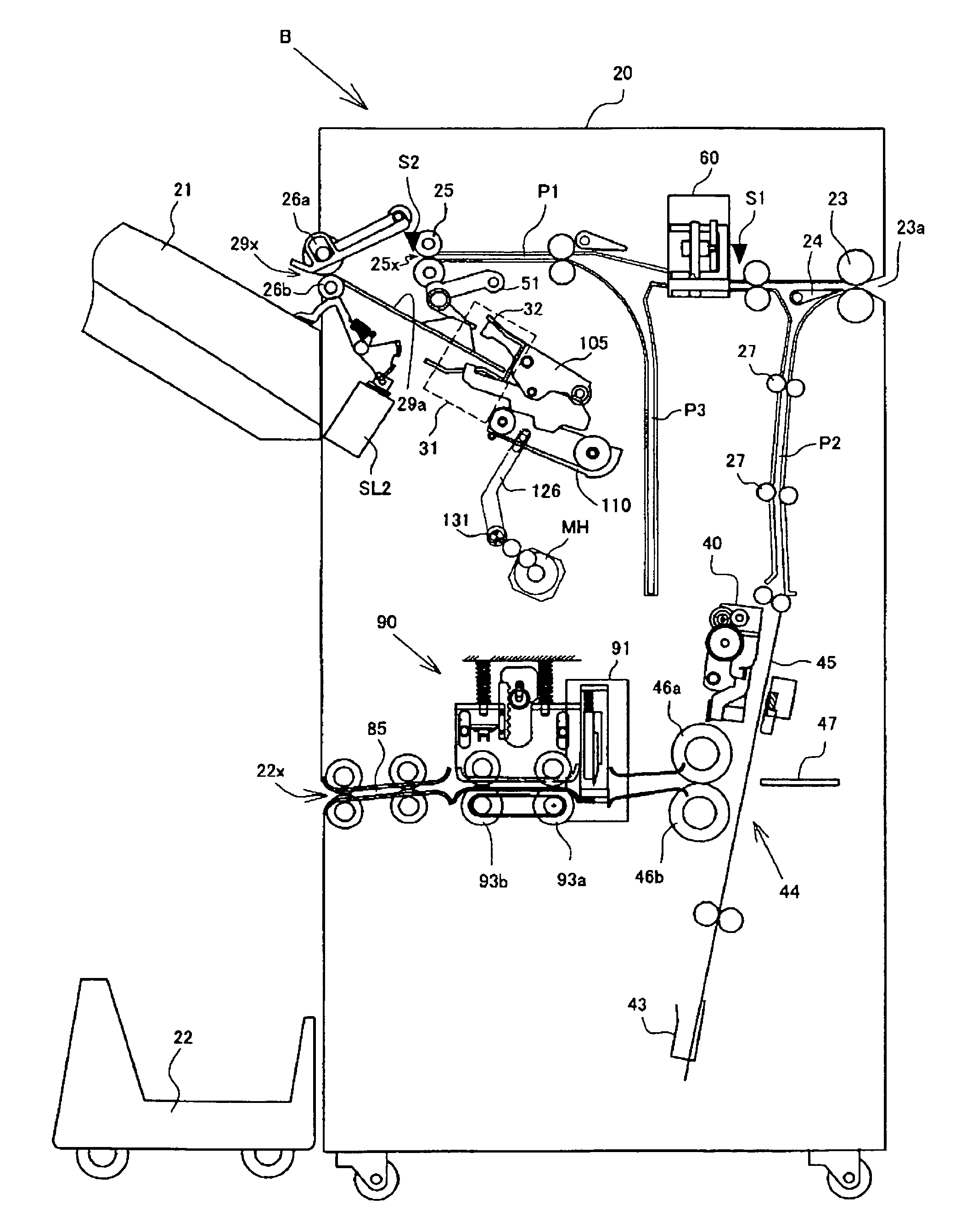
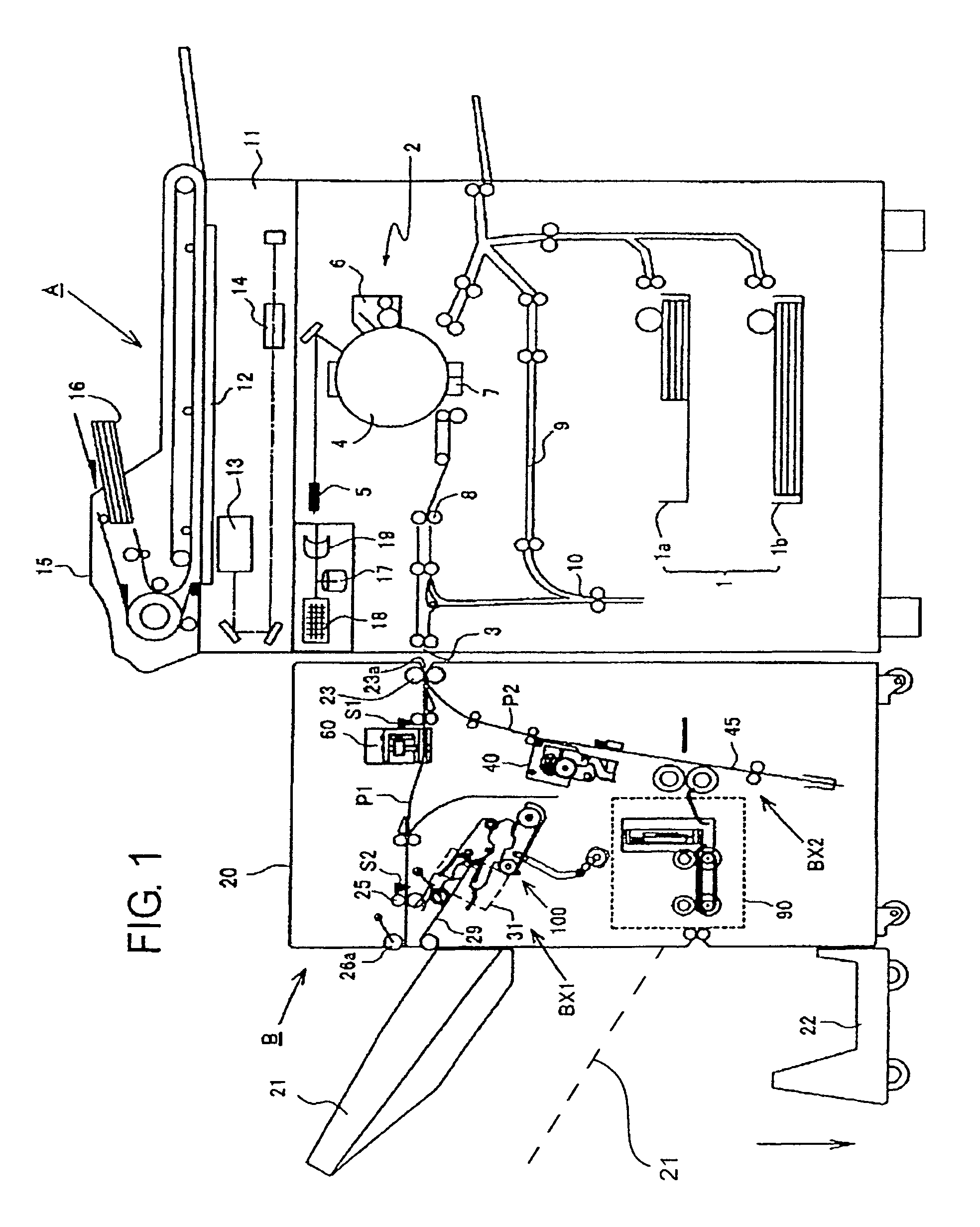
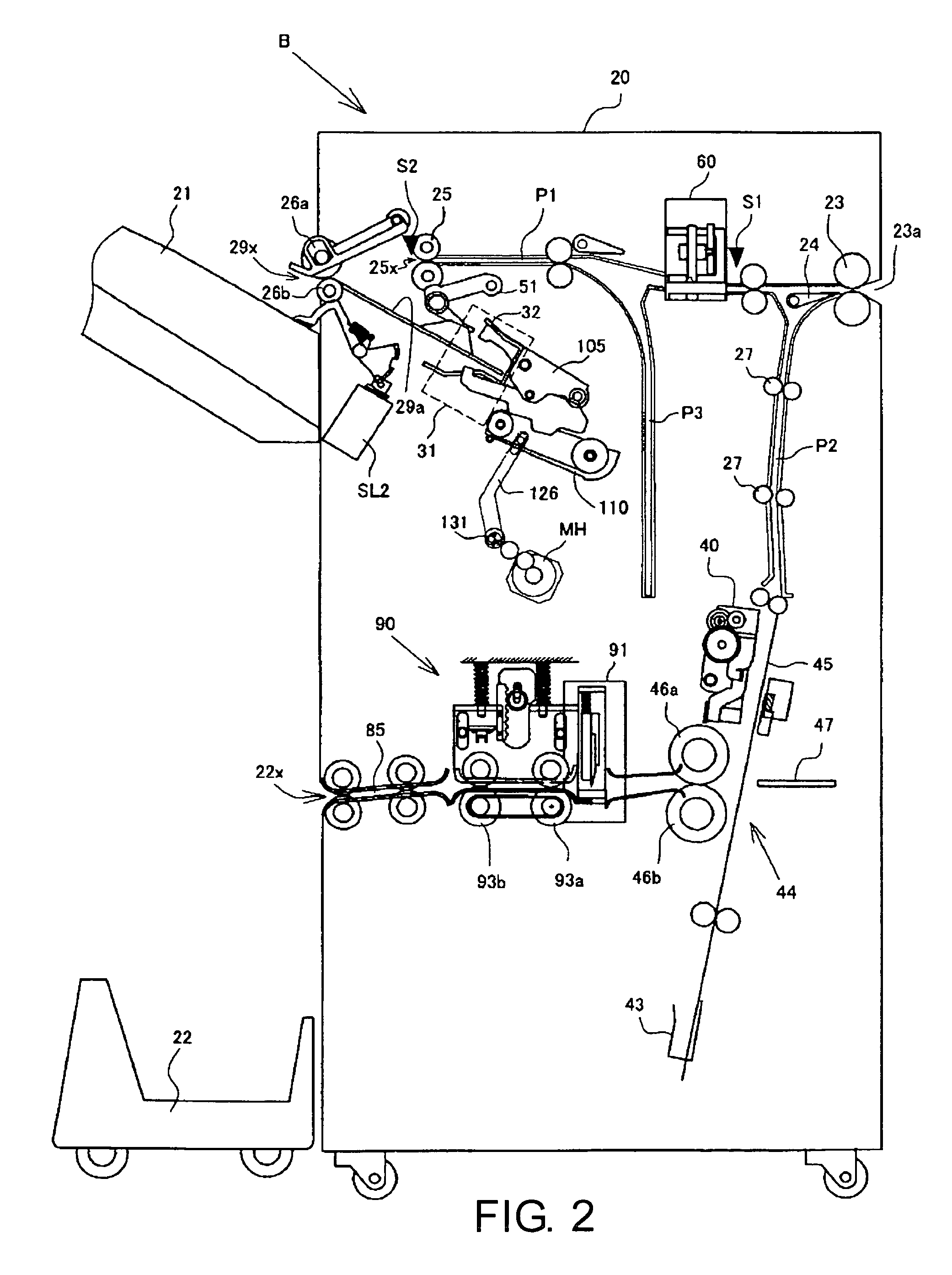
[0049]The present invention will specifically be described below based on preferred embodiments of the invention as shown in accompanying drawings. FIG. 1 is an entire configuration view showing an image formation system provided with an image formation apparatus A and a post-processing apparatus B according to the invention, FIG. 2 is an explanatory view of a detailed configuration of the post-processing apparatus B, and FIG. 3 is an explanatory view of main parts of the apparatus B.

[Configuration of the Image Formation System]

[0050]The image formation system as shown in FIG. 1 is formed of the image formation apparatus A and the post-processing apparatus (sheet processing apparatus; which is the same in the following description) B. Then, a carry-in entrance 23a of the post-processing apparatus B is coupled to a sheet discharge outlet 3 of the image formation apparatus A, and it is configured that sheets with images formed thereon in the image formation apparatus A are stapled in ...


PUM

PropertyMeasurementUnit
heightaaaaaaaaaa
heightaaaaaaaaaa
heightaaaaaaaaaa

Abstract

A sheet post-processing apparatus includes a cutting device for cutting a fore-edge portion of a center-folded bunch of sheets disposed in a position spaced from a sheet discharge outlet to eliminate the risk for inflicting a wound on the body of an operator, an end binding device for gathering sheets received from a carry-in entrance and performing binding processing in the end portion of a bunch of sheets, a saddle-stitching device for gathering sheets received from the carry-in entrance and performing binding processing in the center portion of a bunch of sheets, and a center-folding device for performing center-folding processing on the bunch of sheets subjected to the saddle-stitching processing. A cutting device is subjected to the center-folding processing. A second discharge outlet is disposed in the other side face of the apparatus frame to discharge the bunch of sheets subjected to the center-folding processing in the center-folding device.

Description

BACKGROUND OF THE INVENTION[0001]1. Technical Field[0002]The present invention relates to a sheet post-processing apparatus for sequentially receiving sheets successively fed from an image formation apparatus of, for example, a copier, printer or the like to process in a bunch form, and performing post-processing such as end binding processing, punching processing, saddle-stitching center-folding processing and the like on the bunch of sheets.[0003]2. Description of the Related Art[0004]Conventionally, sheet post-processing apparatuses have been known which gather sheets discharged from an image formation apparatus such as a copier or the like, and perform end binding processing, saddle-stitching center-folding processing to make a booklet, and further, bookbinding processing by applying an adhesive to the spine of a bunch of sheets to attach a front cover. In recent sheet post-processing apparatuses, with improvements in performance of a stapler for performing binding processing, f...

Claims


Application Information

Patent Timeline
Patent Type & Authority Patents(United States)
IPC IPC(8): B65H37/04
CPCB65H37/04B65H45/18B65H45/28G03G15/6544B65H2801/27G03G2215/00831
Inventor OKAMOTO, KOJIOBIKANE, KENKONDO, JUN
Owner COPYER
Learn More