
Lane determining device, method, and program

a technology of determining device and lane, applied in the direction of process and machine control, navigation instruments, instruments, etc., can solve the problems of difficult to recognize the position of the vehicle, gyro sensor, g sensor, and vehicle speed sensor, and not allowing the immediate recognition of which of the branch roads

Active Publication Date: 2012-02-07
AISIN AW CO LTD
View PDF10 Cites 15 Cited by
  • Summary
  • Abstract
  • Description
  • Claims
  • Application Information

AI Technical Summary

Benefits of technology

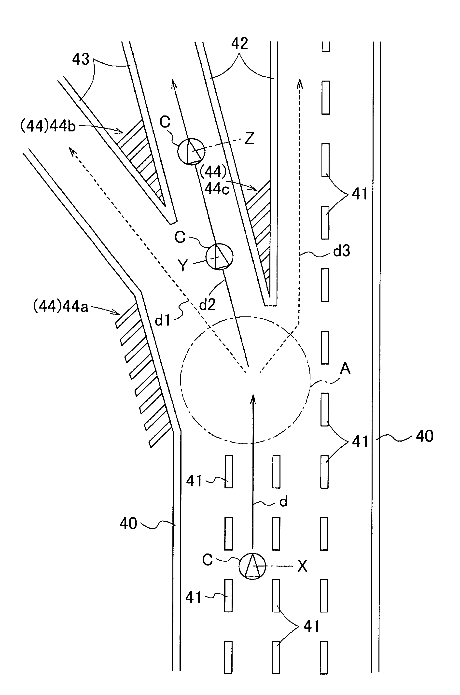
[0009]Various exemplary implementations of the broad principles described herein are capable of quickly determining on which lane the vehicle is traveling after passing through a branch point of a road even if no lane marking as a basis of the recognition of the lane exists before the branch point.

Problems solved by technology

Because of this, information from a conventional GPS (Global Positioning System), gyro sensor, G sensor, and vehicle speed sensor, does not allow the immediate recognition of which of the branch roads the vehicle is traveling after passing through the branch point.
JP-A2000-105898 detects the travel information of the vehicle by obtaining the information regarding the lane markings marked on the road surface of the lane where the vehicle is traveling, and therefore, if, for example, there is no lane marking before the position where the narrow-angle branch point exists, the travel information of the vehicle cannot be detected, which poses a problem that it is difficult to recognize the position of the vehicle immediately after the vehicle passes through the narrow-angle branch point.

Method used


Image

  • Lane determining device, method, and program
  • Lane determining device, method, and program
  • Lane determining device, method, and program

Examples


Embodiment Construction

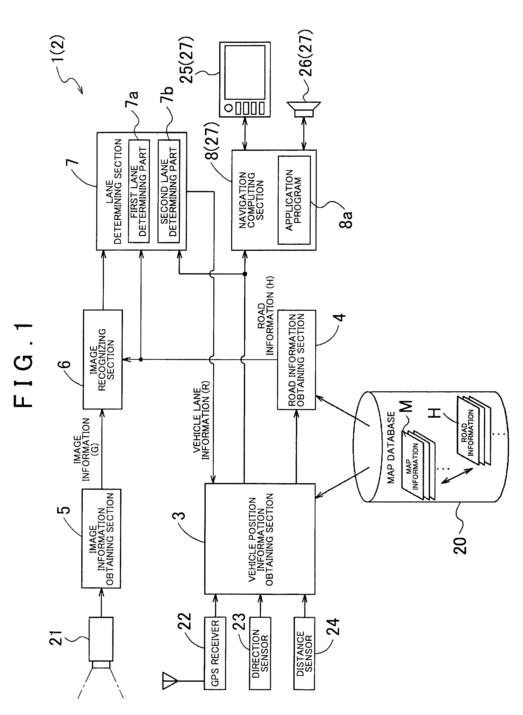
[0023]FIG. 1 is a block diagram schematically showing the configuration of an exemplary navigation apparatus 1 including a lane determining device 2. The lane determining device 2 is capable of determining a vehicle lane (a road lane on which a vehicle C is traveling), based on results of image recognition of lane markings included in obtained image information G (see FIG. 3, FIG. 4, and FIG. 7) and based on road information H obtained from a map database 20. Such lane markings may include solid or dashed lines, or the like, provided as traffic lane border lines on both sides of the lane.

[0024]Further, even immediately after the vehicle C passes through a branch point (see FIG. 5, FIG. 6, and so on) when the above lane determination using the image recognition results is difficult, the lane determining device 2 is capable of quickly determining the vehicle lane on which the vehicle C is traveling, by using results of image recognition of specific lane markings. The navigation appara...


PUM


Abstract

Devices, methods, and programs obtain vehicle position information indicating a current position of a vehicle, and based on the vehicle position information, obtain road information including positions and forms of lane markings around the current position of the vehicle. Based on the road information, the devices, systems, and methods determine whether a branch point exists on the road in a forward direction of the vehicle. If a branch point exists, the devices, methods, and programs obtain image information of an area before the branch point, and determine whether no lane marking is imaged or is partly imaged in the image information of the area before the branch point. If there is no lane marking or only a partial lane marking imaged in the area before the branch point, the devices, methods, and programs obtain image information of the branch point including a captured image of a lane marking, and determine a lane in which the vehicle is traveling after the branch point based on an imaging order of the lane marking, a form of the lane marking, a position of the lane marking in the image information of the branch point, and the road information.

Description

INCORPORATION BY REFERENCE[0001]The disclosure of Japanese Patent Application No. 2007-032352, filed on Feb. 13, 2007, including the specification, drawings and abstract is incorporated herein by reference in its entirety.BACKGROUND[0002]1. Related Technical Fields[0003]Related technical fields include devices, methods, and programs that recognize a lane on which a vehicle is traveling, for example, by using image information including a captured image of at least a lane marking around the vehicle.[0004]2. Related Art[0005]Japanese Patent Application Publication No. JP-A2000-105898 (pages 21-22, FIGS. 24, 25) discloses an on-vehicle navigation apparatus that recognizes the position of a vehicle by using a camera mounted on the vehicle. The apparatus includes a camera capturing an image of a surface of a forward area of a road where the vehicle is traveling. The apparatus detects changes in width of lane markings (white lines) marked on the road surface. The apparatus determines that...

Claims


Application Information

Patent Timeline
Patent Type & Authority Patents(United States)
IPC IPC(8): G05D1/02
CPCG01C21/3602G01C21/3658
Inventor NAKAO, KOICHINAKAMURA, MASAKINAKAMURA, MOTOHIRO
Owner AISIN AW CO LTD
Learn More