Mounting assembly with adjustable spring tension and pivoting lock lever

a technology of adjustable spring tension and pivoting lock lever, which is applied in the direction of weapons, fastening means, rod connections, etc., can solve the problems of rail damage, need to slightly increase initial spring tension, etc., and achieve the effect of reliably controlling the spring tension and mounting reliable

Inactive Publication Date: 2012-02-14
SWAN RICHARD E
View PDF31 Cites 40 Cited by
  • Summary
  • Abstract
  • Description
  • Claims
  • Application Information

AI Technical Summary

Benefits of technology

[0021]Accordingly, it is an object of the present invention to provide an improved mounting assembly that allows for the releasable mounting of various accessories onto the standard dovetail rail found on modern combat weapons. Further, it is an object of the present invention to provide a mounting assembly that can be reliably mounted onto a dovetail rail while including an actuator that includes the ability to adjust the spring tension that is exerted by the clamping foot. It is still a further object of the present invention to provide a mounting assembly having an adjustable actuator that further includes a retention nut that allow a user to predictably and reliably control the spring tension and clamping force of the mounting assembly.

Problems solved by technology

Finally, despite the benefits of a fixed, self-adjusting range of spring tension provided by the prior art device, in certain environments, there is still a perceived need to adjust the range of the spring tension, for example if dovetail rails have excessive wear there may be a need to slightly increase the initial spring tension.
Tighter is not better in these circumstances and over tightening can lead to damage to the rail 22 of the weapon 2.
There is thus a struggle between the benefits of a fixed mounting so as to provide a fixed, self-adjusting range of spring tension, and the perceived need to be able to adjust the range of the spring tension.

Method used


Image

  • Mounting assembly with adjustable spring tension and pivoting lock lever
  • Mounting assembly with adjustable spring tension and pivoting lock lever
  • Mounting assembly with adjustable spring tension and pivoting lock lever

Examples


Embodiment Construction

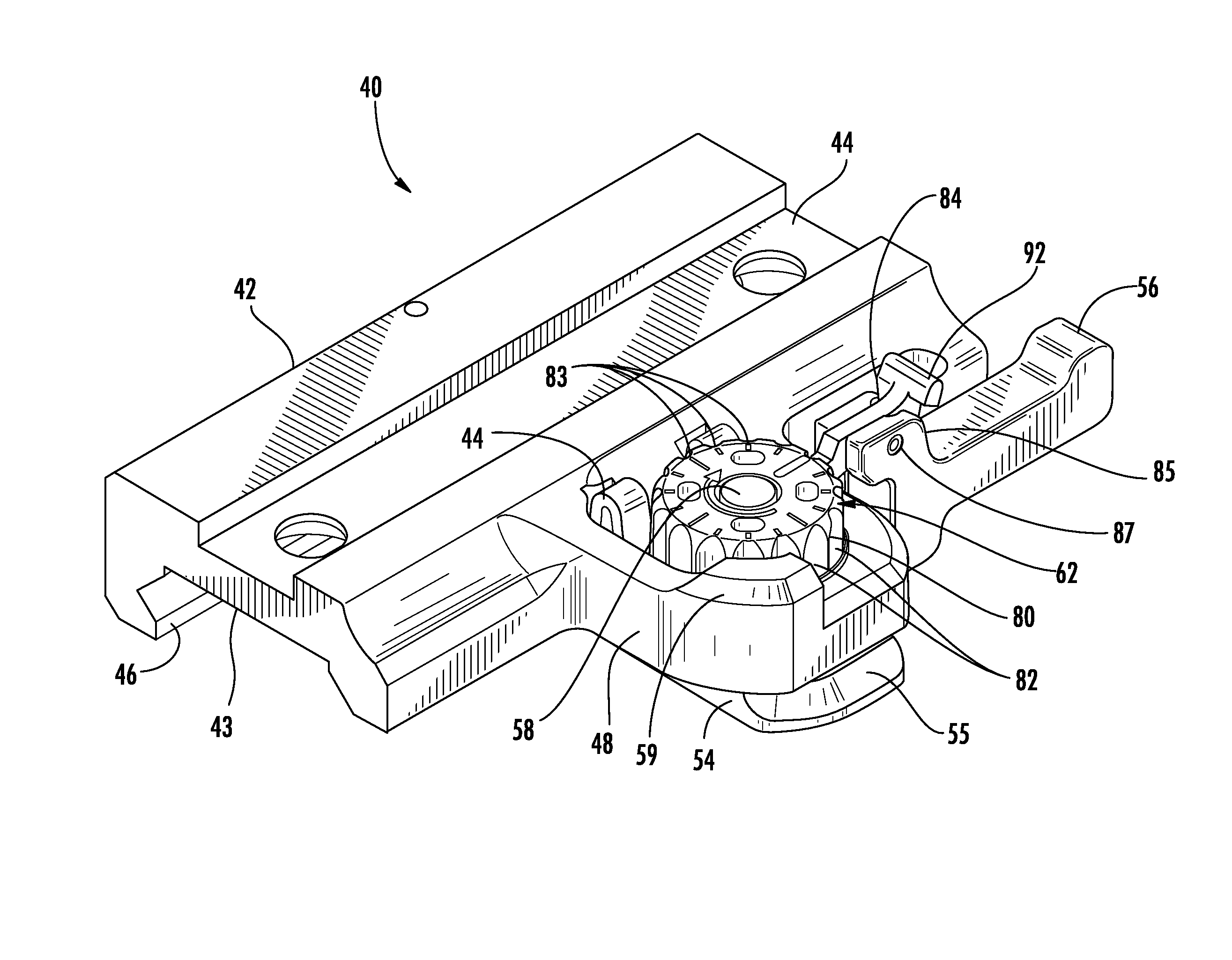
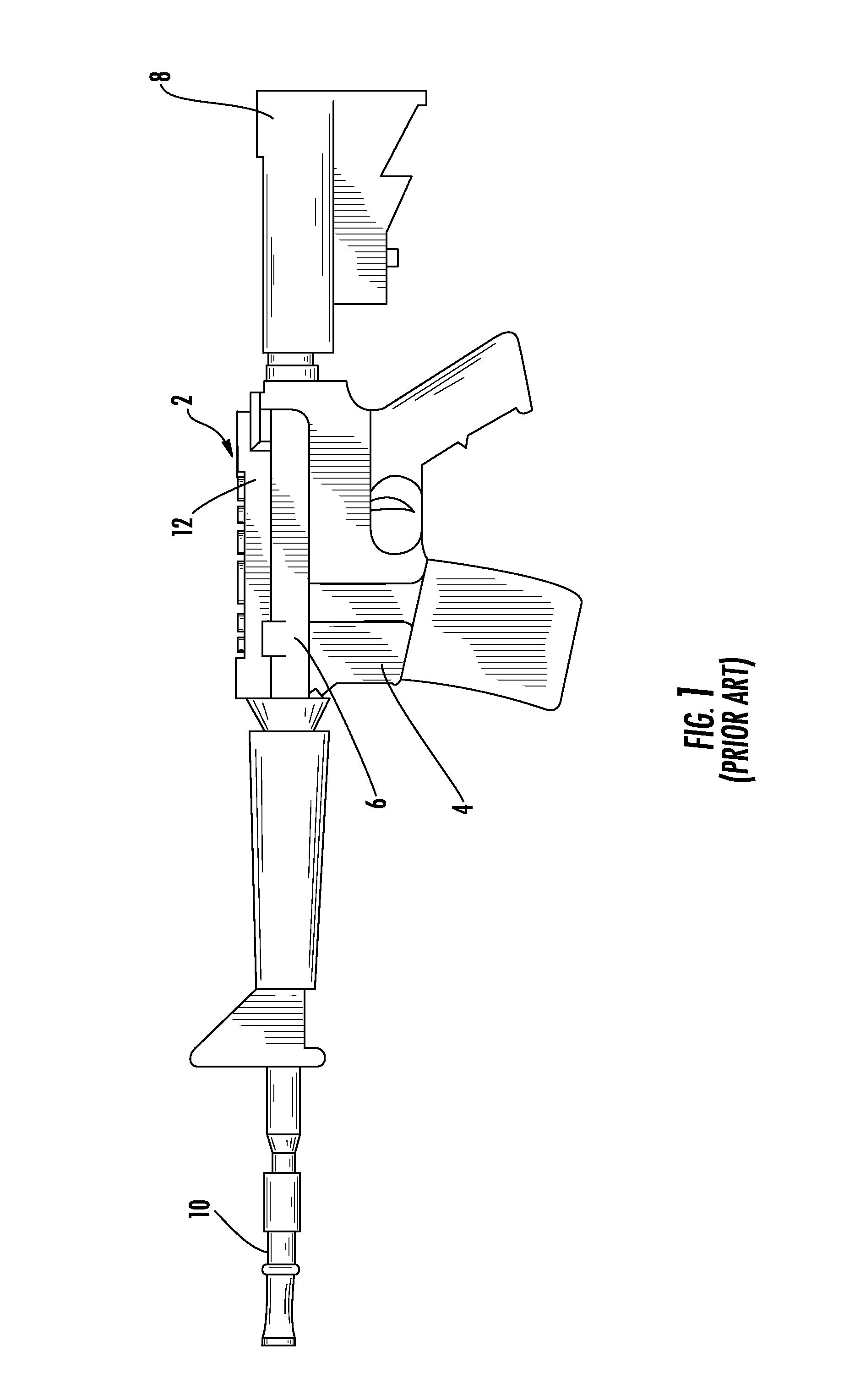
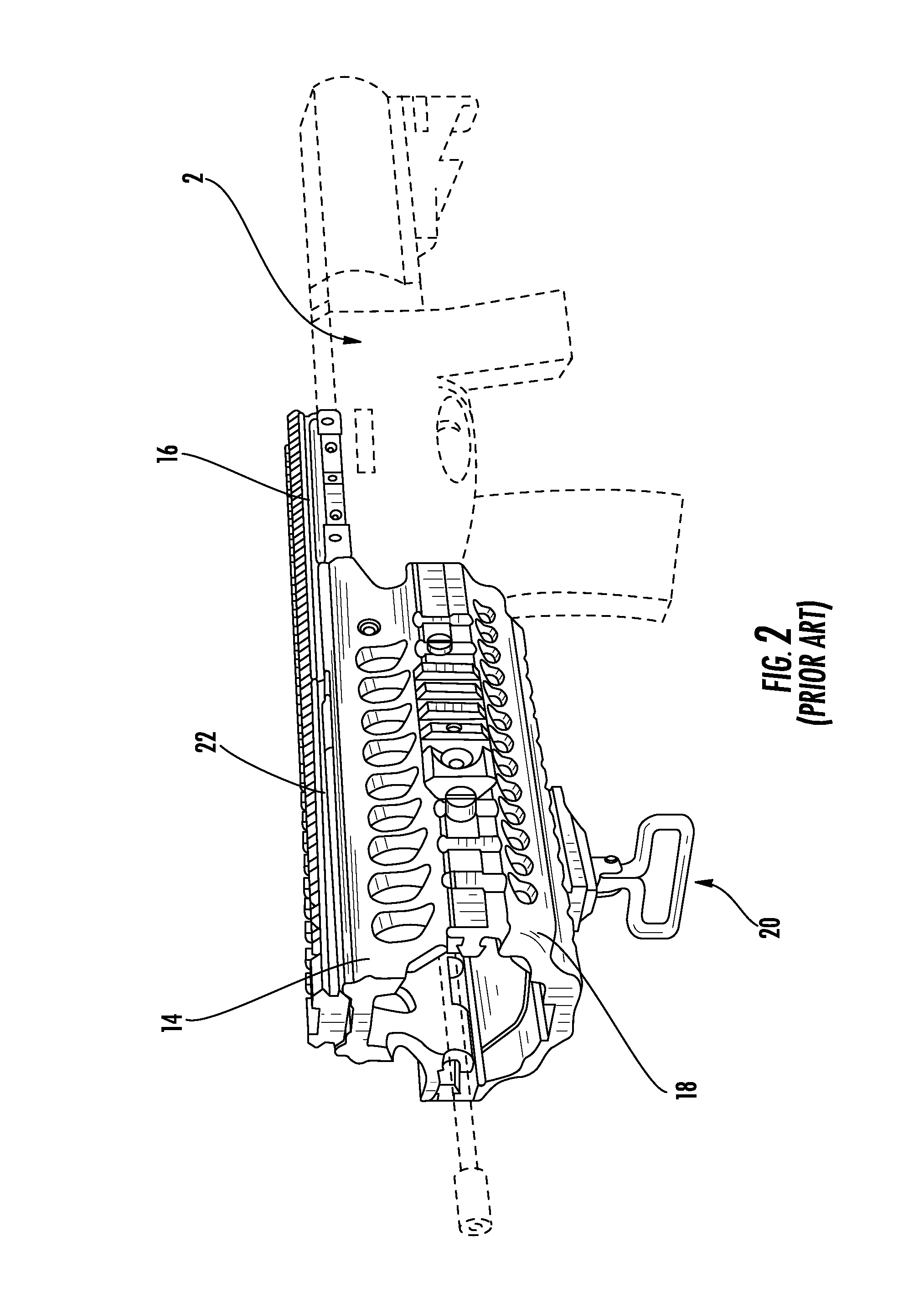
[0035]Now referring to the drawings, the mounting assembly is shown and generally illustrated at 40 in FIGS. 4-10. The mounting assembly 40 is configured to be releasably attached to a standard dovetail rail profile 12 as is depicted in FIG. 1, and includes a means for adjustment to control the clamping force exerted by the mounting assembly 40 against the dovetail rail 12, as will be discussed in more detail below. The mounting assembly 40 of the present invention is particularly suited for use in connection with any firearm 2 that utilizes a standard dovetail rail 12 or the dovetail rail 22 of a supplemental rail system as depicted in FIG. 2. The mounting assembly 40 is also suitable for use with any weapon system or device that utilizes a dovetail rail as a platform for attachment.

[0036]Turning now to FIG. 4, as can be seen, the mounting assembly 40 includes a main body 42 that is configured in substantially the same manner as a traditional prior art device and further includes a...


PUM


Abstract

An improved mounting assembly is provided that is configured to be releasably attached to a standard dovetail rail profile, wherein the initial clamping tension of a clamping assembly is adjustable. The mounting assembly includes a main body having a lower portion that is configured to engage a standard dovetail and an upper portion accessory receiving formation. The lower portion of the mounting assembly has a first engagement member extending downwardly along one side thereof for engaging one side of the dovetail rail and a clamping assembly to engage the opposing side of the dovetail rail. At least one spring and a retention nut are provided as part of the clamping assembly such that retention nut controls the preset spring tension thereby controlling the clamping force applied by the clamping assembly. A lock lever connected to the actuator arm selectively locks the position of the retention nut on the threaded shaft.

Description

CROSS-REFERENCE TO RELATED APPLICATIONS[0001]This application claims priority to earlier filed U.S. Provisional Application Ser. No. 61 / 295,824, filed Jan. 18, 2010, and is a continuation-in-part of U.S. Ser. No. 12 / 271,309, filed on Nov. 14, 2008, now U.S. Pat. No. 7,905,045, which is a continuation-in-part of U.S. patent application Ser. No. 11 / 933,506, filed Nov. 1, 2007, now U.S. Pat. No. 7,757,423, which is related to and claims priority from earlier filed U.S. Provisional Patent Application No. 60 / 864,022, filed Nov. 2, 2006. The entire contents of all earlier filed applications are incorporated herein by reference.BACKGROUND OF THE INVENTION[0002]1. Field of the Invention[0003]The present invention relates generally to modular integrated accessory mounting assemblies for combat weapons. More specifically, the present invention relates to an accessory mounting assembly, which includes a clamping assembly that provides adjustable spring tension to control the clamping force exe...

Claims


Application Information

Patent Timeline
Patent Type & Authority Patents(United States)
IPC IPC(8): F41G1/38
CPCF41G1/387F41G11/003Y10T403/7071
Inventor SWAN, RICHARD E.
Owner SWAN RICHARD E
Why Eureka
Try Eureka