Determining endpoint connectivity of cabling interconnects

a technology of cabling interconnects and endpoints, applied in the field of communication networks, can solve the problems of high cost of space in these environments, complex network deployment and upgrade challenges for providers, and the exact nature of interconnection errors is a very onerous and time-consuming task, so as to reduce the time needed to troubleshoot cabling errors

Inactive Publication Date: 2012-02-14
ALCATEL LUCENT SAS
View PDF13 Cites 10 Cited by
  • Summary
  • Abstract
  • Description
  • Claims
  • Application Information

AI Technical Summary

Benefits of technology

[0013]Some embodiments of the invention include a RFID reader for reading the cable identifier stored in an RFID tag disposed at an end of the communications cable connected to the first I / O port. The RFID reader is part of the near-end system in some embodiments, while in others it is a portable RFID reader communicatively coupled to the near-end system for providing the cable identifier thereto. These embodiments provide an advantage of ease and efficiency in determining the cable identifier through the use of RFID technology.
[0015]Furthermore, in some embodiments the far-end system is further operable to send a connection query message to the near end system; and the near-end system is further operable to receive the connection query message and to respond thereto by creating and sending the near-end message to the far-end system. These embodiments have the advantage of providing the capability to determine endpoint connectivity of a communication cable locally from the far-end system, for example by a craft person, when the far-end system or the end of the communications cable connected thereto is not equipped with RFID technology.
[0017]Advantageously, embodiments of the invention could be used by network and service providers to troubleshoot cabling interconnection problems of communications equipment, both electrical and optical interconnections, as well as other types of electronic systems in general. Important reductions in the time needed to troubleshoot cablings errors may be obtained by addressing the problem of easily and accurately determining the endpoint connectivity of cables interconnecting systems or subsystems of a communications network.

Problems solved by technology

This evolution presents significant challenges to service and network providers, which attempt to serve their clients faster and better, by continuously enlarging and upgrading their networks with a view to serve a growing number of clients and to implement the latest advances in networking technologies.
Because the cost of space in these environments is high, the equipment is commonly organized in the most compact manner that is practical.
As a result, there is often a confusing collection of cabling running through the environment to interconnect the equipment within the respective location (office, cabinet, etc) both to other equipment within the location and to equipment outside of the location.
Network deployment and upgrading presents complex challenges to providers, one of which is managing interconnections between equipment of various size, make and functionality (also referred to here as systems) that make-up the network.
Furthermore, these techniques would also apply to cabling connections of electronic systems in general, in situations where there are numerous systems to be interconnected at a particular installation site and there are a very large number of electrical or optical cables interconnecting them, such that there exists a very real possibility of incorrect connections and wherein determining the exact nature of the interconnection errors would be a very onerous and time consuming task.
However, physical tags may become separated from the cables and the labels may be rendered illegible.
Further, locating a particular tag amongst a great many tagged cables in a crowded environment may be difficult.
Further, designing and manufacturing unique connectors for a very large number of cables is difficult and relatively costly because each can only serve a particular function and production runs tend to be in relatively small numbers.
However, not only does this solution require an OSS or NMS capable of receiving and processing the interconnection information, it also requires that all systems participating in this solution have RFID readers at their port connectors.
Retrofitting or replacing the I / O cards of legacy systems to include the required RFID readers may not be practical or cost-effective in some cases.

Method used


Image

  • Determining endpoint connectivity of cabling interconnects
  • Determining endpoint connectivity of cabling interconnects
  • Determining endpoint connectivity of cabling interconnects

Examples


second embodiment

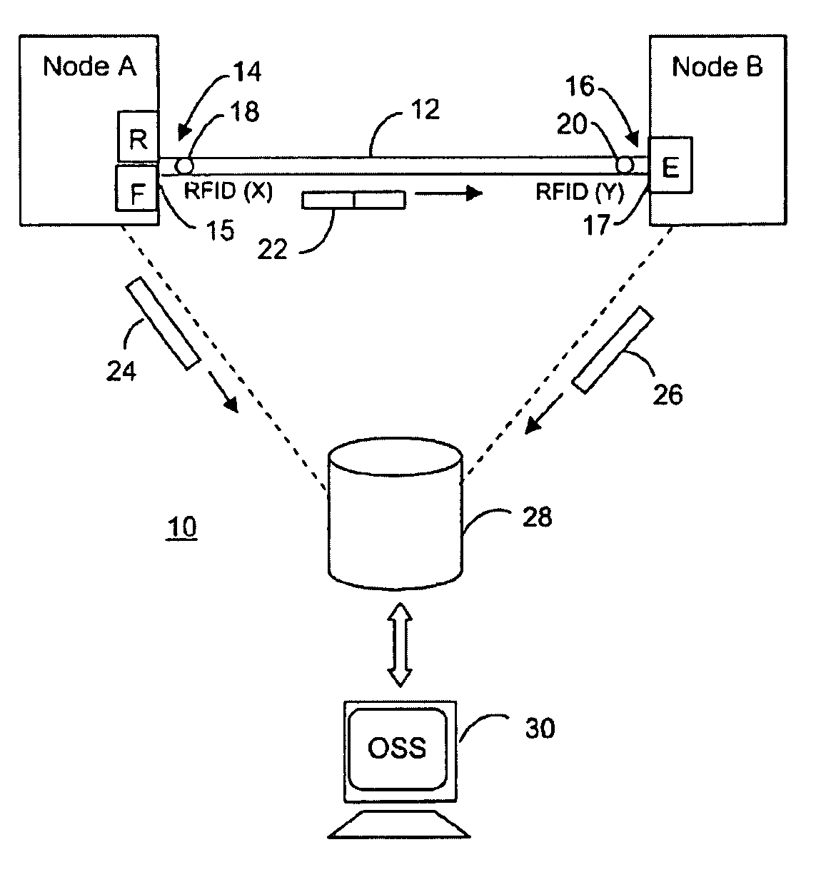
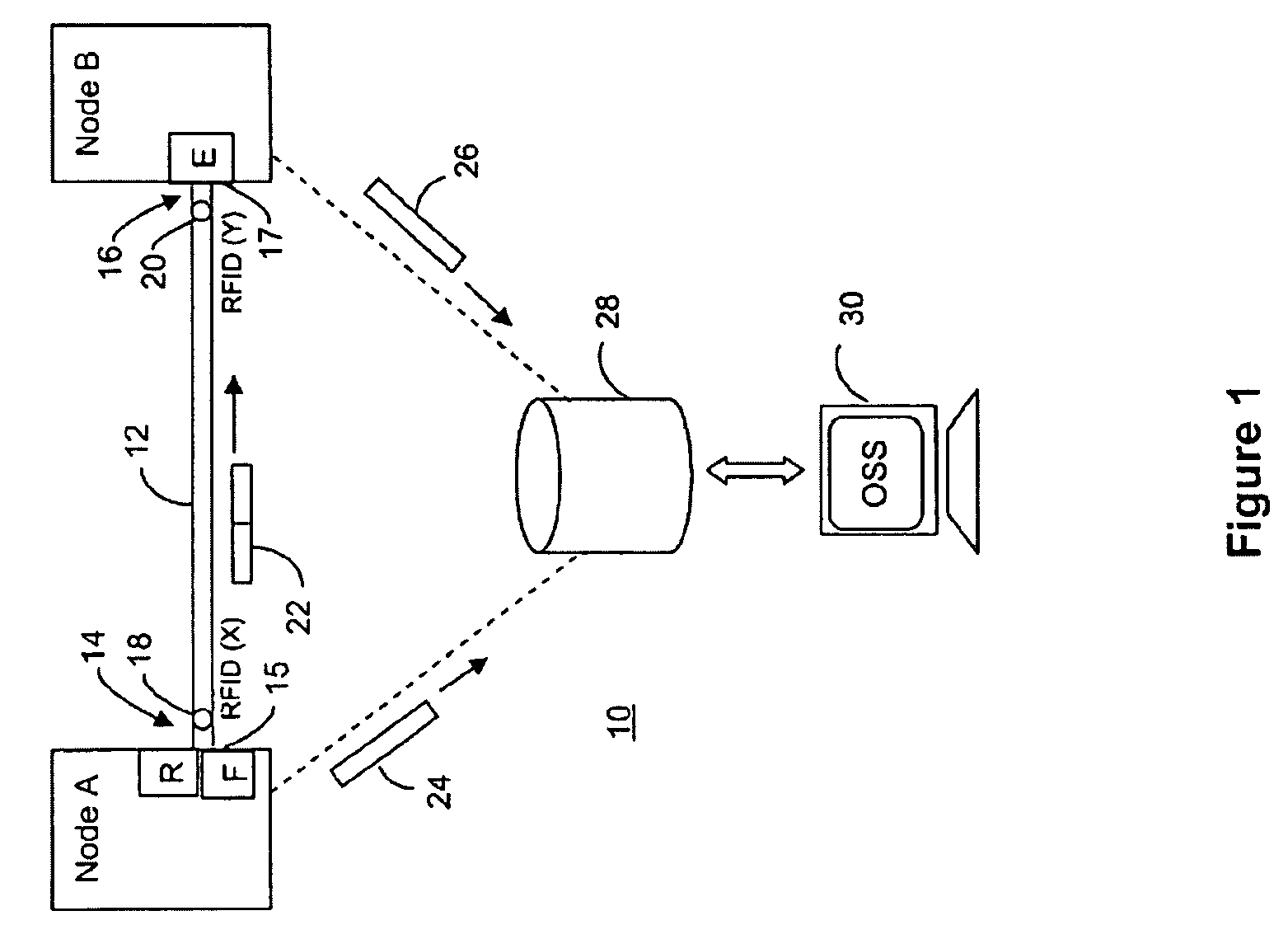
[0028]A further enhancement would be to provide means in the formatter F of the near-end system for selective transmission of the near-end message 22 on a periodic, automatic or manual basis. The periodic mode would be useful for tracking the physical connectivity between systems of a communications network while the automatic mode could be useful for responding to any changes in said connectivity. It should be noted that having the near-end and far-end updates messages sent to the OSS 30 is not essential in that the OSS 30 or network management system could request the information contained in those messages from the those systems in some other format or sequence. For example the information of such messages could be requested singularly or in bulk, the latter being with respect to multiple ports and cables, or over multiple time periods, or both. Further, it should be noted that the OSS 30 or network management system is not essential to the operation of the invention, which point...

first embodiment

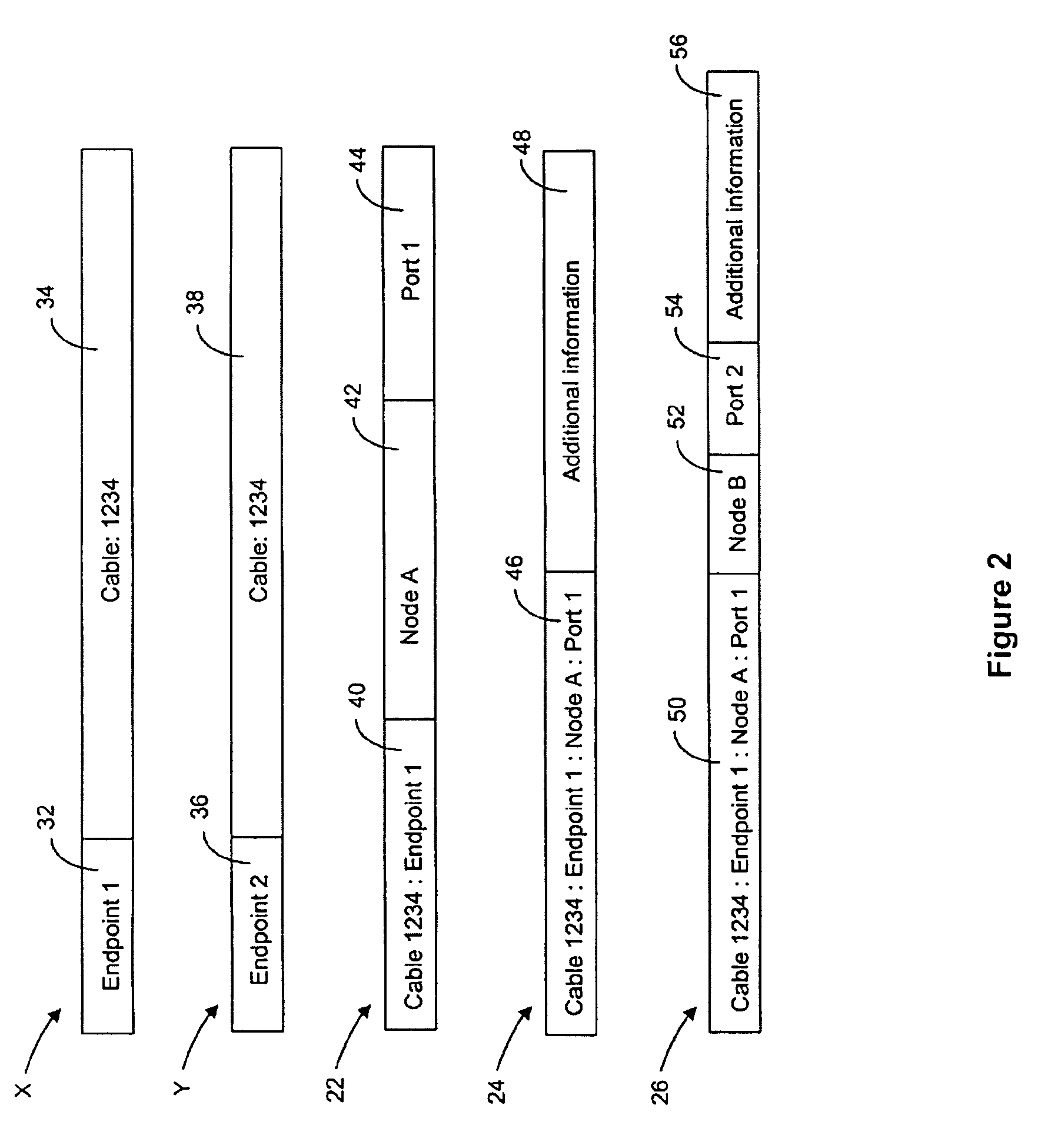
[0029]With reference to FIG. 2, the format and content of the messages and identifiers of the first embodiment will now be described in more detail. As shown in the figure, the first cable identifier X includes a first field 32 containing the unique endpoint label, Endpoint 1, and a second field 34 containing the unique cable label, Cable 1234. The endpoint label is unique to the cable and the cable label is unique to the network, or in the case where the cable connects subsystems of the same system, the latter may be unique to only that system. To avoid any confusion, preferably the cable label is unique to the premises of the network operator at which the near-end and far-end systems are installed. Likewise, the second cable identifier Y includes a first field 36 containing the unique endpoint label, Endpoint 2, and a second field 38 containing the unique cable label, Cable 1234.

[0030]Further with reference to FIG. 2, the near-end message 22 includes the cable endpoint identifier ...


PUM


Abstract

In a communication network or system, cables that interconnect systems or subsystems are provided with RFID tags embedded or affixed at least at one endpoint of each cable. An installed or portable RFID reader in the proximity of an RFID tag of a given cable enables a unique cable endpoint identifier contained in the RFID tag to be read. The identifier is combined with a unique port identifier of the port to which the cable endpoint is attached at the message is sent to a far-end system or subsystem connected to the other end of the cable. That system reads the message and the information contained therein along with a unique port identifier of its own port connected to the given cable, enables positive confirmation of the communicative connection between the two ports and also the cable providing the connection. It also enables communication of the physical routing information to an operations support system for cable management.

Description

FIELD OF THE INVENTION[0001]The invention is directed to communication networks, in particular to methods and apparatus for determining the connection of cable endpoints to input / output (I / O) ports of communications systems interconnected by communications cables, such connection also referred to hereinafter as cable endpoint connectivity.BACKGROUND OF THE INVENTION[0002]Evolution of network technologies resulted in a world of interconnected networks where businesses and households are now amazingly close to eachother. The notion of “network” turns out to be central to our times: the Internet, LANs, WANs, enterprise networks, home networks, etc. are today interconnected over the World Wide Web, changing our lives and the way we do business. This evolution presents significant challenges to service and network providers, which attempt to serve their clients faster and better, by continuously enlarging and upgrading their networks with a view to serve a growing number of clients and t...

Claims


Application Information

Patent Timeline
Patent Type & Authority Patents(United States)
IPC IPC(8): G08B13/14H04Q5/22
CPCH04Q9/00H04Q2209/47
Inventor LANGE, ANDREW SNOWDENNELSON, SCOTT WILLIAM
Owner ALCATEL LUCENT SAS
Why Eureka
Try Eureka