Toner supplying roller, developing apparatus, and image forming apparatus

a technology of developing apparatus and toner supply roller, which is applied in the direction of electrographic process apparatus, instruments, optics, etc., can solve the problems of image defects, change of toner state, and decrease in flowability of toner, so as to prevent image defects

Active Publication Date: 2012-02-14
CANON KK
View PDF8 Cites 5 Cited by
  • Summary
  • Abstract
  • Description
  • Claims
  • Application Information

AI Technical Summary

Benefits of technology

[0009]Therefore, it is an object of the present invention to provide a toner supplying roller, a developing apparatus, and an image forming apparatus which prevent image defects due to excess or shortage of toner supply through a life of a developing apparatus.

Problems solved by technology

However, in a laser beam printer (LBP) using toner of a low viscoelasticity, the state of the toner may change (e.g., flowability of toner may decrease) depending upon the use conditions thereof or the number of sheets to be used, as the use of the developing apparatus progresses.
When the opening ratio is large, the image defects may be caused by an excess supply of the toner to the developing roller when the developing apparatus is new.
When the opening ratio is small, the image defects may be caused due to shortage of the toner supply as the use of the developing apparatus progresses.
Therefore, it becomes very difficult to appropriately set the opening ratio of the toner supplying roller.

Method used


Image

  • Toner supplying roller, developing apparatus, and image forming apparatus
  • Toner supplying roller, developing apparatus, and image forming apparatus
  • Toner supplying roller, developing apparatus, and image forming apparatus

Examples


embodiments

Embodiment 1

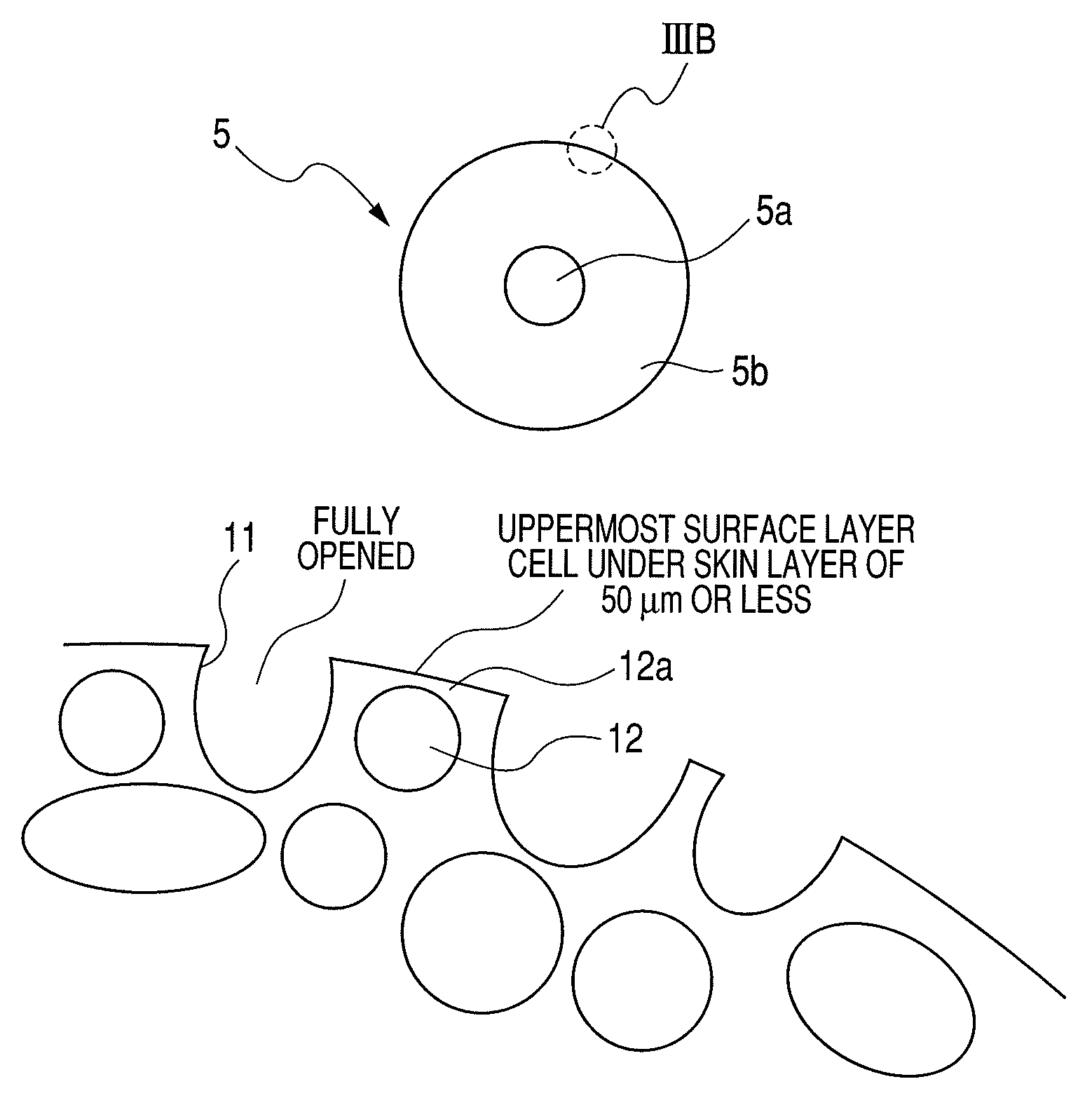
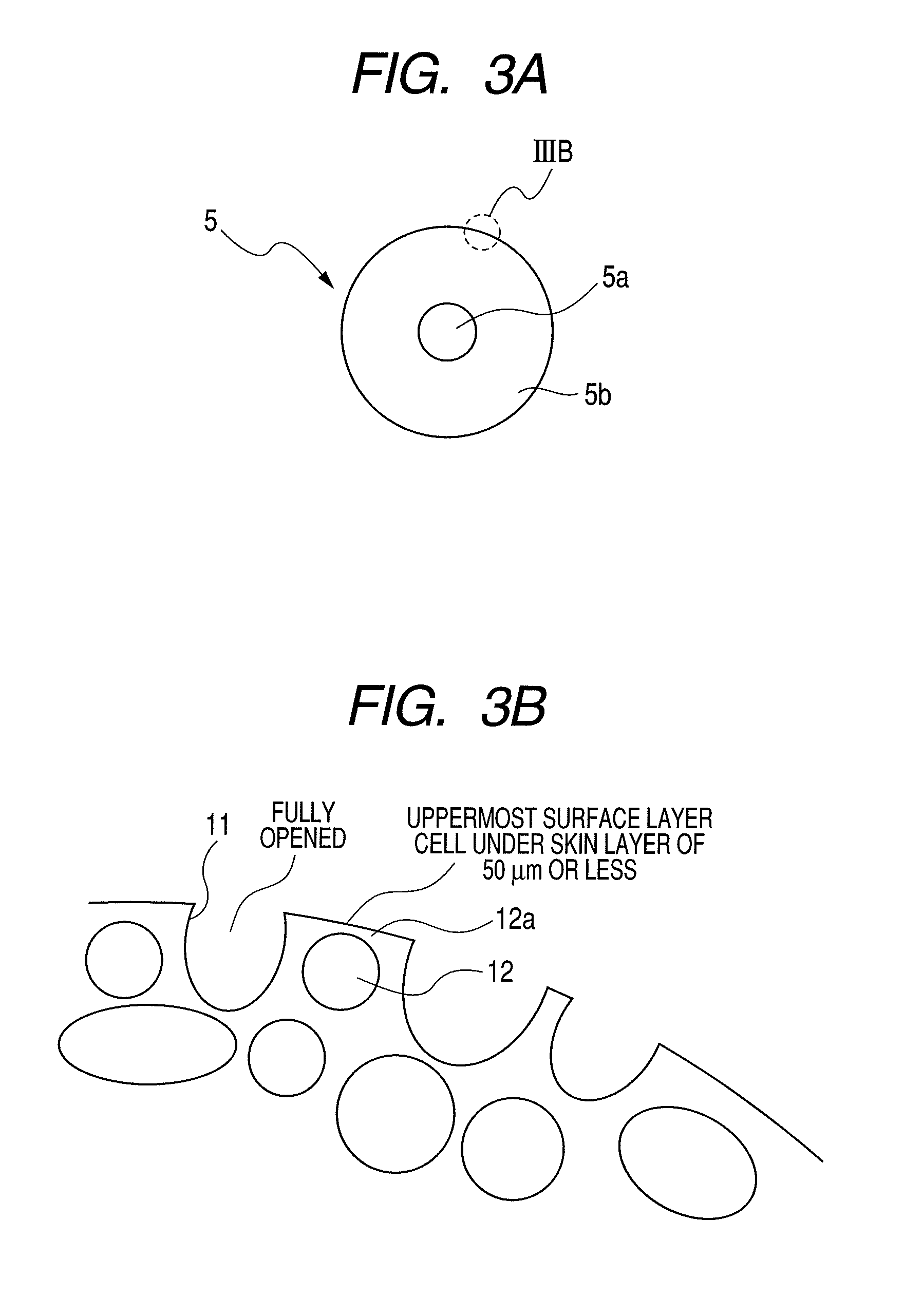
[0017]A toner supplying roller of the present invention includes a toner containing portion containing toner as a developer, a toner supplying roller, and a developing roller (toner carrying member), and is mounted in a developing apparatus that supplies toner to an electrostatic latent image on the surface of a photosensitive member to form a toner image. As an example of such a developing apparatus, there is a laser printer illustrated in FIG. 1.

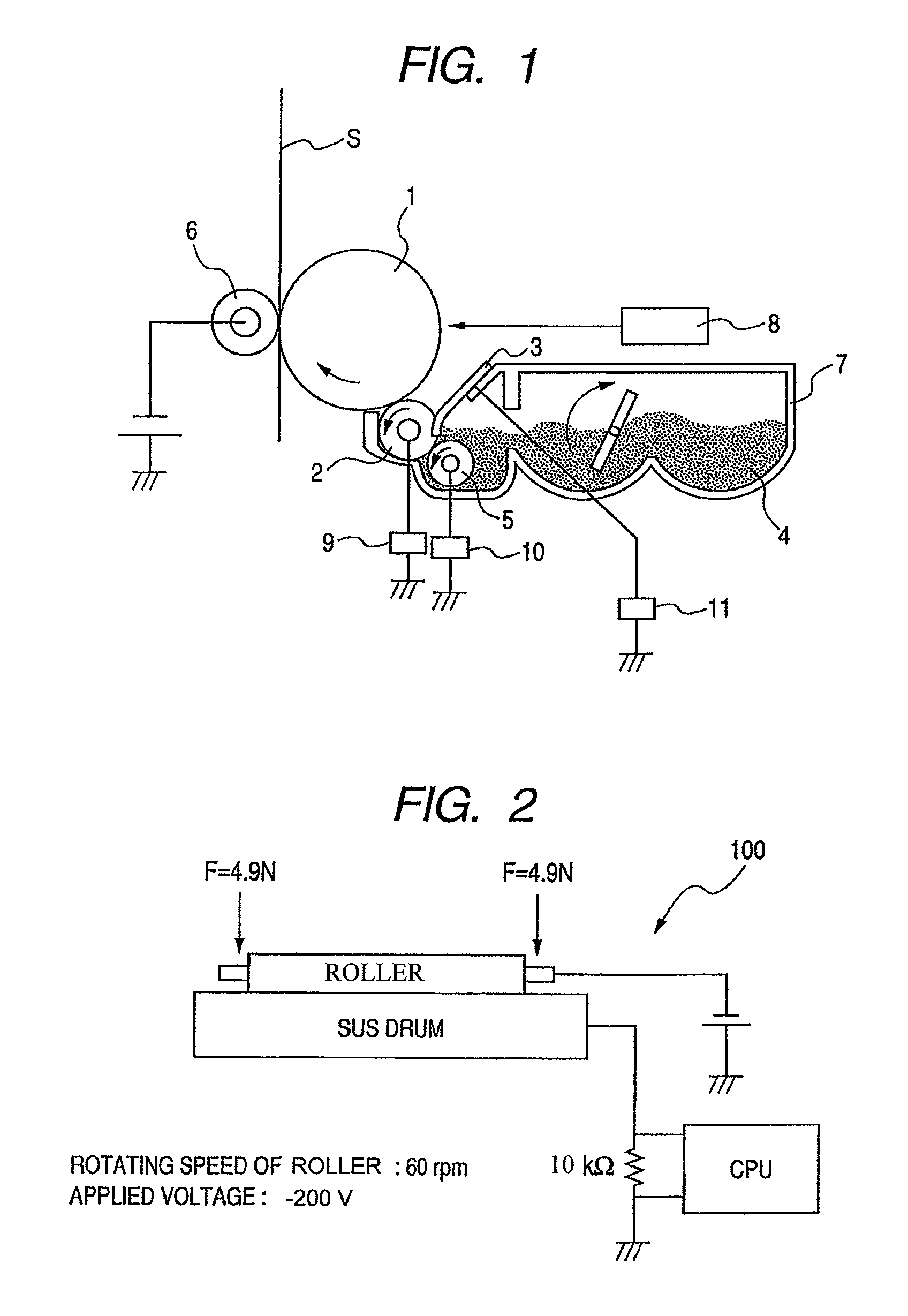
[0018]FIG. 1 is a schematic cross-sectional view illustrating a configuration of an image forming apparatus of the present invention. An image forming process by a reversal development of the present invention will be described briefly with reference to FIG. 1. First, a photosensitive drum (an image carrying member) 1 is uniformly charged negatively by a charging roller (not shown). Next, the surface of the photosensitive drum 1 is exposed to laser light of a scanner 8, which is an image-forming unit, whereby an electrostatic l...

embodiment 2

[0043]Next, another embodiment of the image forming apparatus according to the present invention will be described.

[0044]In Embodiment 2, there is no means for applying a supply bias to the developing roller in the developing apparatus described in Embodiment 1. In this embodiment, a bias of −300 V is applied to the developing roller, and thus, the potential of the developing roller is the same as that of the supplying roller. Further, in this embodiment, a bias of −400 V is applied to the developing blade. In this case, there is no toner supplying electric field from the supplying roller to the developing roller by a bias, and hence the relationship between the opening ratio and the defects of images are different from that in Embodiment 1. In this case, a larger supply ability by the toner supplying roller itself is required, which is as shown in Table 3. Those results are obtained by using a conventional toner supplying roller.

[0045]

TABLE 3Solid imageFoggingfollow-up failureOpeni...


PUM


Abstract

A toner supplying roller which is used in a developing apparatus and has the following characteristics: (1) an average diameter of a foam cell opening portion on a surface of a foam elastic member is 100 to 800 μm, (2) an unopened cell closed by a skin layer of a film thickness of 50 μm or less is present in the surface of the foam elastic member, and (3) assuming that a surface area of the foam elastic member is A, a total area of the foam cell opening portions is B, and a surface area of the unopened cell is C, the following relationship is satisfied:BA+0.2≦B+CA≦0.95.

Description

BACKGROUND OF THE INVENTION[0001]1. Field of the Invention[0002]The present invention relates to a toner supplying roller in a developing apparatus in an image forming apparatus employing an electrophotographic printing method or an electrostatic recording method, a developing apparatus, and an image forming apparatus.[0003]2. Description of the Related Art[0004]In an image forming apparatus such as an electrostatic copying machine and a printer, a latent image on a photosensitive member is developed into a developer image by toner that is a developer from a developing roller of a developing unit and visualized. In this case, in the developing unit, toner conveyed with being agitated is supplied onto the developing roller by a supplying roller. Then, the toner is conveyed to a developing portion where the photosensitive member and the developing roller are opposed to each other, with a thickness of a toner layer being adjusted by a toner regulating member (hereinafter, referred to a...

Claims


Application Information

Patent Timeline
Patent Type & Authority Patents(United States)
IPC IPC(8): G03G15/09
CPCG03G15/0808
Inventor KOYANAGI, MASATOKATAGIRI, SHINJIYOSHIDA, MASAHIROHASHIMOTO, KAZUNORIYAMAUCHI, HISASHI
Owner CANON KK
Why Eureka
Try Eureka