

LED lighting apparatus with swivel connection
a technology of led lighting apparatus and swivel connection, which is applied in the direction of lighting and heating apparatus, semiconductor devices for light sources, gas-filled discharge tubes, etc., can solve the problems of short service life, high power consumption, and short service li
- Summary
- Abstract
- Description
- Claims
- Application Information
AI Technical Summary
Problems solved by technology
Method used
Image

Examples
first embodiment
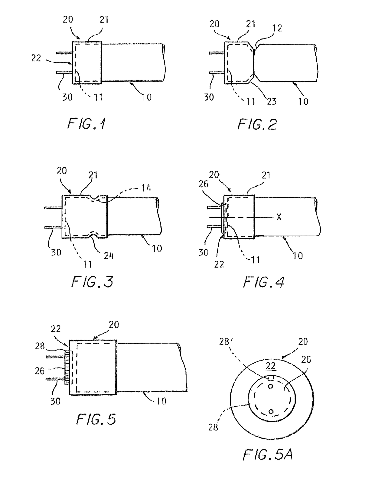
[0025]the LED lighting apparatus with swivel connectors is illustrated in FIG. 1. The housing 10 for at least one LED (not shown) is depicted by broken lines. The end 11 of the housing 10 is capped with an end cap 20. The end cap 20 is friction-fitted onto the end of the housing. The end cap 20 has a sidewall 21 that surrounds the end 11 of the housing 10 and a surface 22 that spans the sidewall 21. From the surface 22 extend at least two pin connectors 30 that connect the housing to a standard fluorescent or incandescent light fixture (not shown). The pin connectors 30 are inserted into the socket or sockets of the lighting fixture. Once the pin connectors 30 are secure in the sockets of the light fixture, the housing 10 can be rotated relative to the end caps 20 with the application of rotational force on the housing. This rotational force can direct the light from the LEDs to illuminate the desired surface or area. The friction fit of the end cap 20 on the housing end 11 allows f...
third embodiment
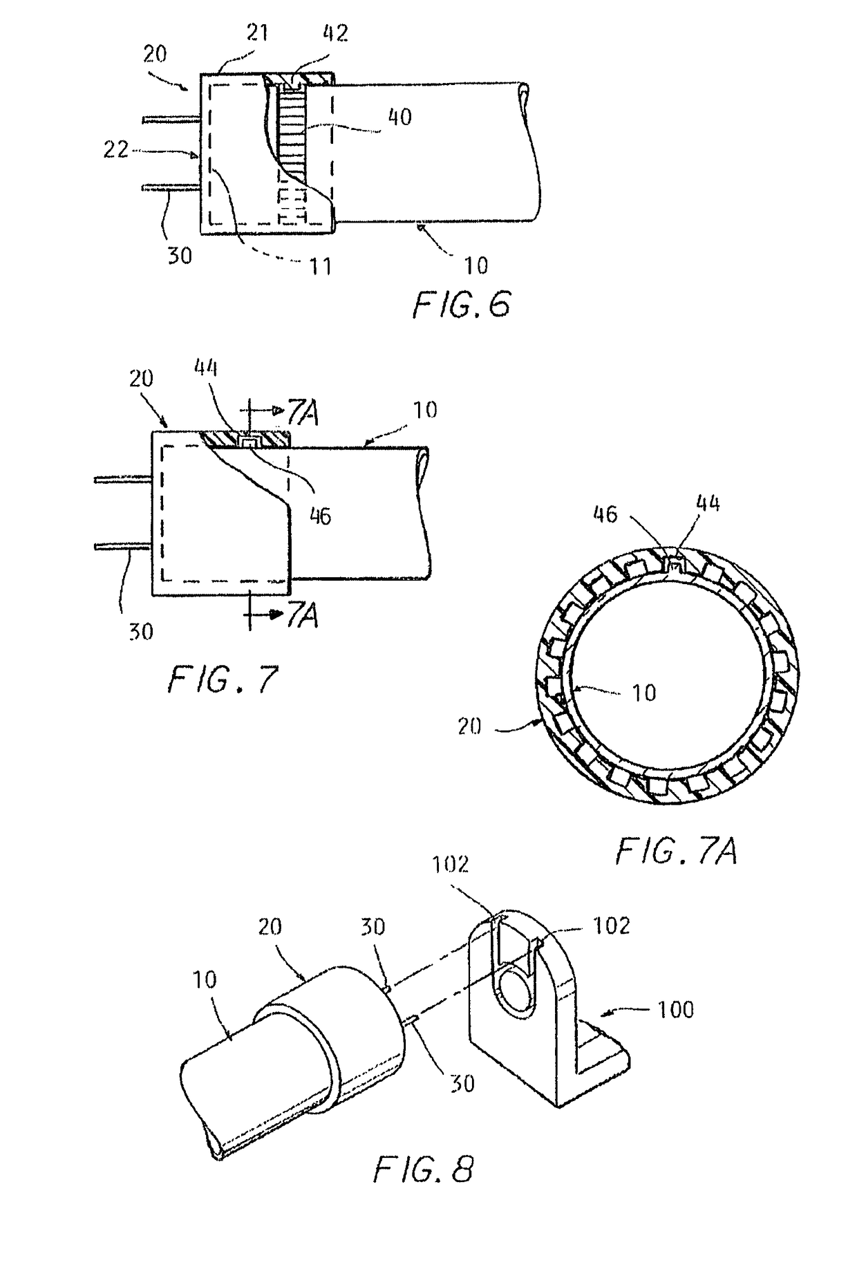
[0037]the LED lighting apparatus with swivel connections is illustrated in FIG. 6. In FIG. 6, the housing 10 for at least one LED (not shown) is again depicted by broken lines. The end 11 of the housing 10 is capped with an end cap 20. The end cap 20 has a sidewall 21 that surrounds the end 11 of the housing 10 and a surface 22 that spans the sidewall 21. Extending from the surface 22 are at least two pin connectors 30 that connect the housing to a standard fluorescent or incandescent light fixture (not shown). The pin connectors 30 are inserted into the socket or sockets of the lighting fixture.
[0038]In FIG. 6 the housing 10 has a ratchet gear 40 positioned a distance in from the end 11 of the housing 10. The ratchet gear 40 is positioned so that the teeth of the gear are flush with the housing 10. The sidewall 21 of the end cap 20 has a pawl 42 that is positioned to correspond to the ratchet gear 40 when the end cap 20 is positioned on the end 11 of the housing 10. The end cap 20,...
second embodiment
[0042]Alternative configurations of the stop are contemplated. One such example involving the ratchet of the second embodiment incorporates locating teeth in only a portion of the ratchet gear 40, 44 so that the pawl is prevented from further rotation along the ratchet gear 40, 44. Based on the teachings herein, it should be recognized by those skilled in the art that these stop configurations are provided by way of example and not limitation, and that other suitable stop configurations may be used.
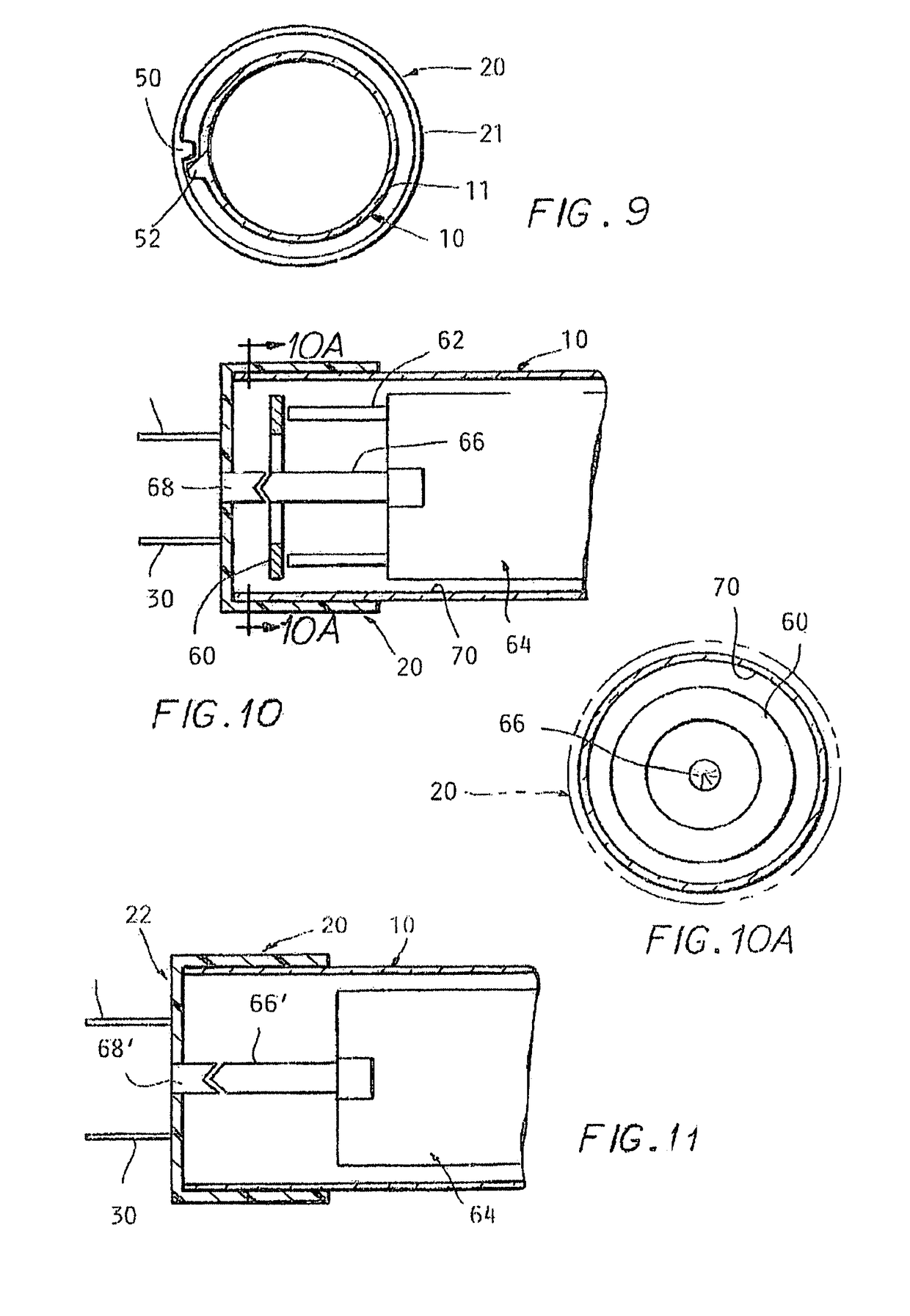
[0043]Other ways to prevent twisting of the electrical connections due to rotation of the housing 10 or housing 10 and end cap 20 may be used. One such embodiment incorporates the use of slip rings as illustrated in FIG. 10. The slip ring 60 comprises a conductive circle or band mounted within the housing 10. Electrical connections 62 from the LED array or LED circuit board 64 are made to the slip ring 60 and are omitted here for clarity. A spring loaded center contact 66, located along t...
PUM
 Abstract
Description
Claims
Application Information