Multi-stage hyper-velocity kinetic energy missile

a kinetic energy missile and hyper-velocity technology, applied in direction controllers, instruments, weapons, etc., can solve the problems of inconvenient discarding or modification of tow infrastructure, ineffective against modern composite armour, and high cost of hyper-velocity propellants, etc., to reduce the weight of propellant, save propellant, and effective guidance and maneuvering

Active Publication Date: 2012-02-21
RAYTHEON CO
View PDF14 Cites 4 Cited by
  • Summary
  • Abstract
  • Description
  • Claims
  • Application Information

AI Technical Summary

Benefits of technology

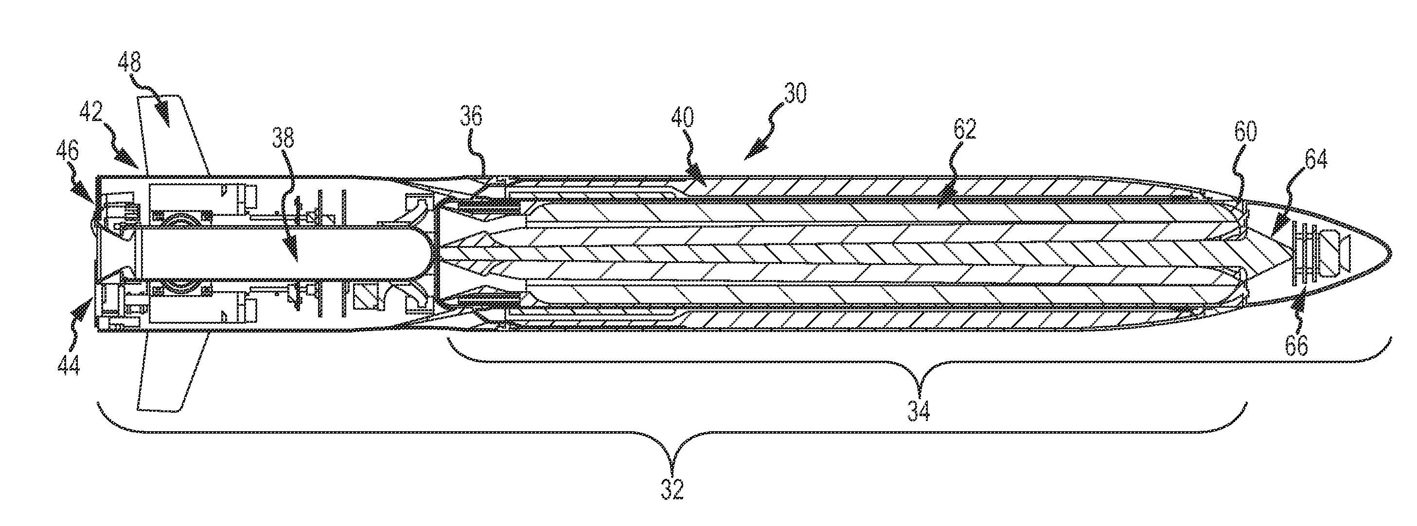
[0013]This is accomplished with a ‘missile in a missile’ architecture in which the hyper-velocity KE missile (HVKEM) includes a 1st stage flight missile and a 2nd stage kill missile that includes a KE-rod penetrator. The flight missile cruises at a relatively low velocity (less than Mach 1.5) to conserve propellant (weight) and to allow for effective guidance and maneuvering until the missile is in close proximity to the target. In general, guidance of the flight missile may be CLOS, fire-and-forget etc. When the missile is within the lethal range of the KE-rod penetrator, the kill missile separates and boosts to a much higher velocity (greater than Mach 3) and flies unguided to impact the target in less than a second. Waiting to boost the KE-rod until “the last second” reduces the propellant (weight) needed to deliver the KE-rod on target and simplifies the guidance.
[0014]In a TOW-compatible configuration, the flight missile includes launch and flight motors to fly the HVKEM at less than Mach 1.5 and typically sub-sonic velocities and a CLOS flight control subsystem to maneuver the missile to the target in response to guidance commands received from the CLOS system on the TOW platform. Non-smokey propellant can be used to achieve and sustain velocities less than Mach 1.5. The kill missile includes a range sensor to detect when the target is within lethal range of the KE-rod penetrator to trigger separation of the kill missile from the flight missile and ignition of a boost motor to boost the kill missile to >Mach 3 and typically hyper-velocity to impact the target. The lethal range is limited to a few hundred meters from impact such that separation occurs less than 1 second prior to impact. At this range, no additional guidance of the KE-rod is required or is practical. Consequently, the smokey propellants used to achieve greater than Mach 3 and hyper-velocities do not pose a problem. The combination of only boosting the kill missile to hyper-velocity and waiting to do so until less than one second to impact allows the ‘missile in a missile’ design to satisfy the physical size and weight constraints, operational constraints and the CLOS guidance constraints while delivering the KE-rod on target at sufficient velocity to kill the target.

Problems solved by technology

The standard TOW missiles have been widely used against armour in the past and still have a role but are less effective against modern composite armour.
The cost of discarding or modifying the TOW infrastructure is simply prohibitive.
Furthermore, the propellants required for hyper-velocity are very ‘smokey’ which occludes the operator's vision of the target.
These missiles are heavy, 100 lbs or more and CLOS is not effective for the same reasons of hyper-velocity and the smoke cloud and additionally because the small diameter rod does not support the required beacons.
With the repeated failure of different KE architectures to both satisfy the TOW physical, operational and guidance constraints while providing effective KE performance the industry is largely resigned that KE technology cannot be effectively retrofitted to the TOW platform.
The consensus is that the amount of propellant required for hyper-velocity flight will violate the size and weight constraints and that hyper-velocity flight is incompatible with CLOS guidance.

Method used


Image

  • Multi-stage hyper-velocity kinetic energy missile
  • Multi-stage hyper-velocity kinetic energy missile
  • Multi-stage hyper-velocity kinetic energy missile

Examples


Embodiment Construction

[0024]The present invention provides a multi-stage hyper-velocity kinetic energy (KE) missile. The missile may be configured for use with different platforms and different guidance systems but is particularly well suited for use with the existing base of TOW launch containers and platforms satisfying all of the physical, operational and guidance constraints while maintaining the performance of the KE-rod penetrator.

[0025]This is accomplished with a ‘missile in a missile’ architecture in which the hyper-velocity KE missile (HVKEM) includes a 1st stage flight missile and a 2nd stage kill missile that includes a KE-rod penetrator. The flight missile cruises at a relatively low velocity (less than Mach 1.5) to conserve propellant (weight) and to allow for effective guidance and maneuvering until the missile is in close proximity to the target. Guidance of the flight missile may be CLOS, fire-and-forget etc. When the missile is within the lethal range of the KE-rod penetrator, the kill m...


PUM


Abstract

A multi-stage hyper-velocity kinetic energy missile (HVKEM) uses a ‘missile in a missile’ architecture in which the HVKEM includes a 1st stage flight missile and a 2nd stage kill missile that includes a KE-rod penetrator. The flight missile cruises at a relatively low velocity (less than Mach 1.5, typically less than Mach 1) to conserve propellant (weight) and to allow for effective guidance and maneuvering until the missile is in close proximity to the target. When the missile is within the lethal range of the KE-rod penetrator, the kill missile separates and boosts to a much higher velocity (greater than Mach 3, typically greater than Mach 5) and flies unguided to impact the target in less than a second. Waiting to boost the KE-rod until “the last second” reduces the total propellant (weight) needed to deliver the KE-rod on target and simplifies the guidance. The missile may be configured for use with different platforms and different guidance systems but is particularly well suited for use with the existing base of TOW launch containers and platforms satisfying all of the physical, operational and CLOS guidance constraints while maintaining the performance of the KE-rod penetrator.

Description

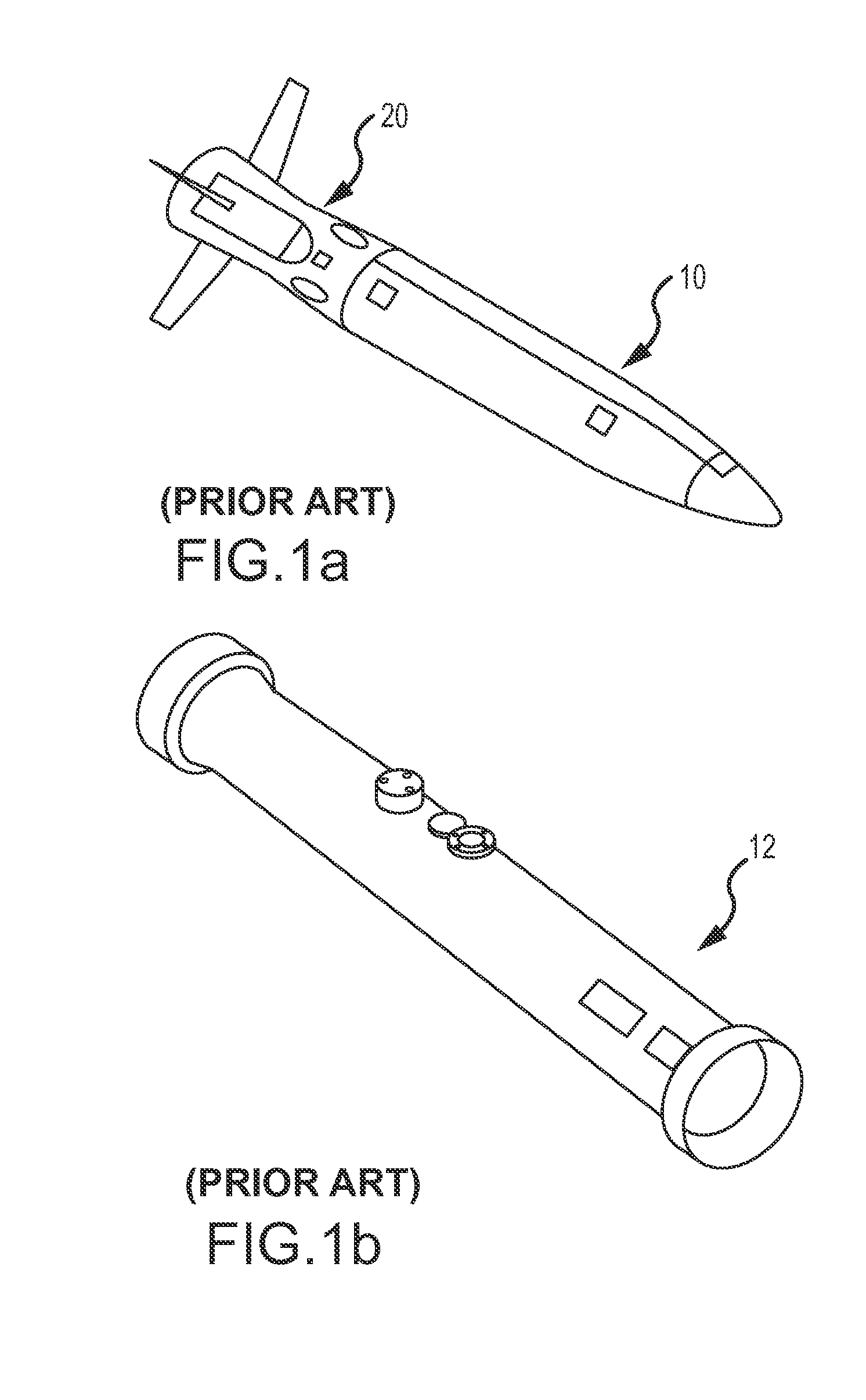
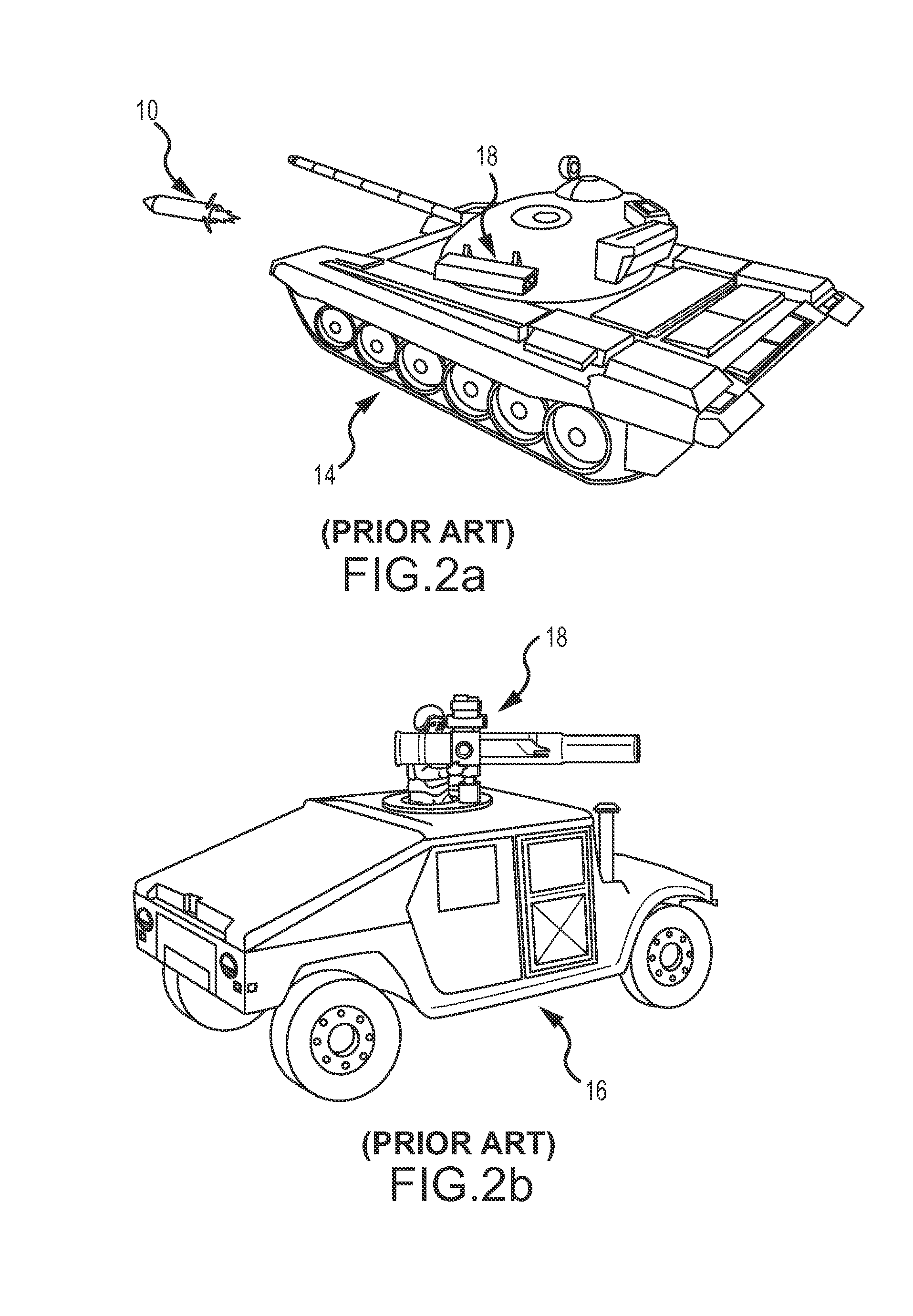
CROSS-REFERENCE TO RELATED APPLICATIONS[0001]This application claims benefit of priority under 35 U.S.C. 119(e) to U.S. Provisional Application No. 61 / 102,094 entitled “Multi-Stage Hyper-Velocity Kinetic Energy Missile” and filed on Oct. 2, 2008, the entire contents of which are incorporated by reference.BACKGROUND OF THE INVENTION[0002]1. Field of the Invention[0003]This invention relates to a multi-stage hyper-velocity kinetic energy (KE) missile. The missile may be configured for use with different platforms and different guidance systems but is particular well suited for use with a class of tactical missiles including an existing base of Tube-Launched, Optically-Tracked, Wire-Guided (TOW) launch platforms using command line of sight (CLOS) guidance to provide hyper-velocity KE-rod penetrator capability.[0004]2. Description of the Related Art[0005]The TOW missile was first produced in 1970 and is the most widely used anti-tank guided missile in the world. As shown in FIGS. 1a-1b ...

Claims


Application Information

Patent Timeline
Patent Type & Authority Patents(United States)
IPC IPC(8): F42B15/01F42B12/32F42B15/04F42B15/00F42B12/00
CPCF41G7/32F42B12/06F42B12/625F42B15/01F42B15/04
Inventor JANIK, RICHARDSTRASSMAN, DORON
Owner RAYTHEON CO
Why Eureka
Try Eureka