
System for filling bags with sand

a sandbag and bag technology, applied in the field of sandbag filling system, can solve the problems of inability to include a self-propelled automatic sandbag filling device with construction, system is extremely cumbersome for individuals, and excessive time consumption

Active Publication Date: 2021-07-20
CURTISS GORDON +1
View PDF15 Cites 0 Cited by
  • Summary
  • Abstract
  • Description
  • Claims
  • Application Information

AI Technical Summary

Benefits of technology

The present invention provides a system for filling bags with sand that eliminates the need for users to manually shovel sand. This system allows for quick and efficient filling of bags, especially in times of emergency preparation or flood prevention. It includes a motor with multiple drive speeds, allowing users to easily maneuver through any terrain and collect sand. The device is user-friendly and efficient, reducing the time and effort required to fill sandbags by hand. It is also affordable and easy to maintain.

Problems solved by technology

None of them, however, include a self-propelled automatic sandbag filling device with construction similar to an auger-driven snow blower which may include multiple drive speeds, electric start, high traction tires, and a steel frame and platform.
It is also known that sand can be extremely cumbersome to gather and fill into bags.
This system is extremely cumbersome for individuals and exceptionally time consuming.
Therefore, there is a need to provide a system for filling bags with sand that is efficient and effortless to operate.
However, it differs from the present invention because the U.S. Pat. No. 5,893,260 reference provides a configuration that is complicated to use and not cost efficient for individuals in need of a system to fill sand bags in the case of a natural disaster preparation activities for storms, floods, and the like.

Method used


Image

  • System for filling bags with sand
  • System for filling bags with sand
  • System for filling bags with sand

Examples


Embodiment Construction

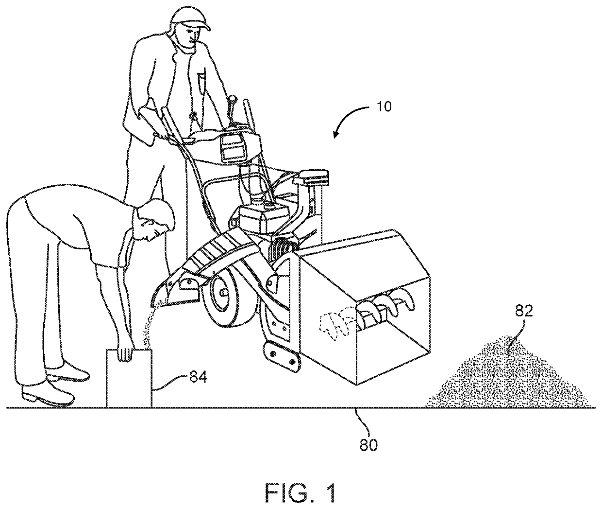
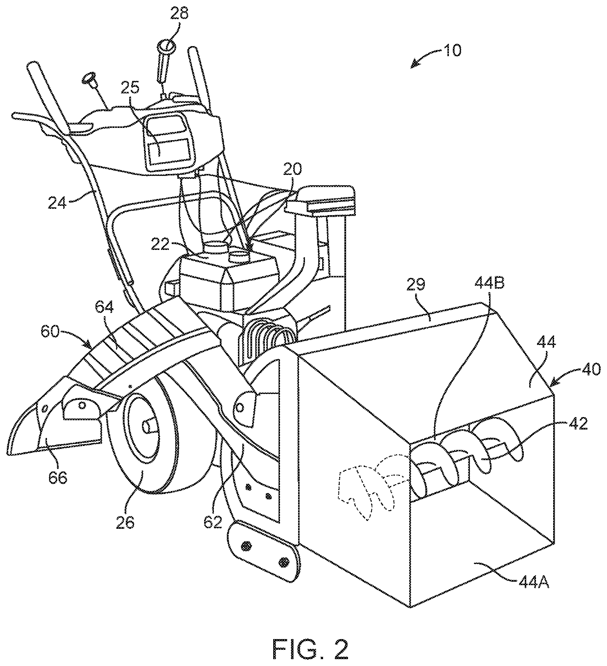
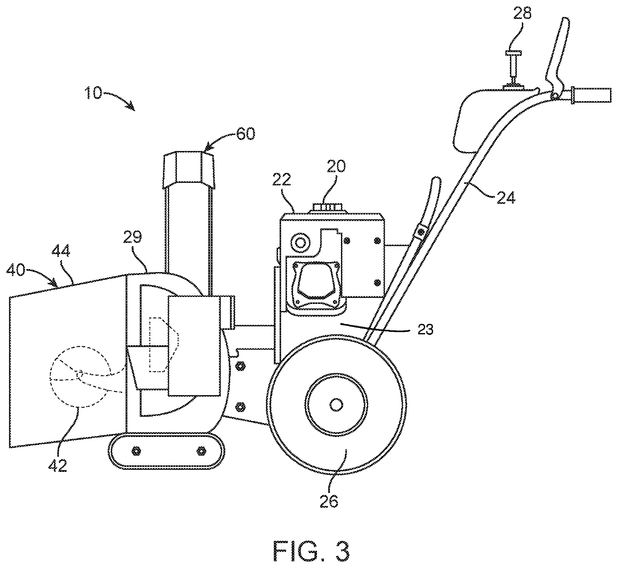
[0018]Referring now to the drawings, where the present invention is generally referred to with numeral 10, it can be observed a system for filling bags with sand 10 that basically includes a motor assembly 20, an auger assembly 40, and a chute assembly 60.

[0019]Motor assembly 20 includes a motor 22, a platform 23, a steel frame 24, and wheels 26, and user controls 28. Motor 22 is securely mounted onto the top of platform 23 of steel frame 24. Furthermore, steel frame 24 includes at least two wheels 26 being mounted to steel frame 24. Additionally, steel frame 24 includes a vertical portion wherein said user controls 28 may be located. User controls 28 are located on said steel frame 24 to allow a user to control the speed at which motor 22 operates. Motor 22 is mounted to steel frame 24 using known methods in the art such as fasteners, welding, and the like. In one embodiment, a steel body 29 may be mounted to a front end of platform 23. Steel body 29 may resemble the front end of a...


PUM


Abstract

A system for filling bags with sand including a motor assembly, an auger assembly, and a chute assembly is enclosed herein. The motor assembly includes a motor and a frame having wheels attached to the frame. The motor is configured to provide a user with multiple drive speeds to provide maximum maneuverability. The motor is communicably connected to the auger assembly having an auger enclosed around a body being cubic in shape. The auger assembly is configured to effortlessly and efficiently intake large amounts of sand as a user operates the motor. The sand then collected by the auger assembly is transferred to the chute assembly. The chute assembly comprises a first portion and a second portion to aid an assistant in filling bags with sand. The first portion and the second portion are directionally adjustable to further aid an assistant in collecting sand.

Description

BACKGROUND OF THE INVENTION1. Field of the Invention[0001]The present invention relates to a system for filling bags with sand and, more particularly, to a system for filling bags with sand that includes a motor, an auger, and an adjustable chute to aid a user in quickly and efficiently fill sandbags.2. Description of the Related Art[0002]Several designs for a system for filling bags with sand have been designed in the past. None of them, however, include a self-propelled automatic sandbag filling device with construction similar to an auger-driven snow blower which may include multiple drive speeds, electric start, high traction tires, and a steel frame and platform. It is known that individuals have a need to fill bags with sand in the event of storm preparations and flood prevention activities. It is also known that sand can be extremely cumbersome to gather and fill into bags. Individuals often use a shovel to manually pick up sand to then fill into sand bags. This system is ext...

Claims


Application Information

Patent Timeline
Patent Type & Authority Patents(United States)
IPC IPC(8): B65B1/12B65B67/04
CPCB65B1/12B65B67/04
Inventor CURTISS, GORDONCURTISS, BARBRA
Owner CURTISS GORDON
Learn More