Passive ballast device, system and methods of using same

a technology of passive ballast and ballast device, which is applied in the field of ballast system, can solve the problems of increased drag, inability to adjust the ballast, and inability to operate autonomous underwater vehicles, etc., and achieve the effect of reducing vehicle size, complexity and power consumption

Active Publication Date: 2022-05-10
WOODS HOLE OCEANOGRAPHIC INSTITUTION
View PDF17 Cites 0 Cited by
  • Summary
  • Abstract
  • Description
  • Claims
  • Application Information

AI Technical Summary

Benefits of technology

[0011]An object of the present invention is to provide an improved ballast system for stationary or mobile submerged vehicles which reduces vehicle size, complexity and power consumption.
[0012]Another object of the present invention is to increase autonomy of such vehicles.
[0014]Yet another object of the present invention is to facilitate low-power hovering and efficient maneuvering, and to extend vehicle range within a liquid body.
[0024]The passive ballast hovering and maneuvering system invention is a device and method for submerged vehicles that allows them to achieve and maintain a desired depth in a liquid body with less power consumed, extending operation time and range. Preferred embodiments of the present invention utilize a small, low power vehicle (e.g. an AUV) with turning moment capable motor, a passive ballast system and autonomous, pre-programmed passive navigation system.
[0025]The passive ballast system is enabled by taking advantage of the pressure of a liquid, especially seawater, brackish water and / or fresh water, in a liquid body. The passive ballast system is compressed when exposed to increasing depths (and pressures) of a liquid body, reducing the vehicles volume and therefore buoyancy, allowing the vehicle to remain at the predetermined depth without any additional buoyancy compensation components.
[0032]The passive ballast system drives a buoyancy change by changing the vehicle's displacement. Meaning that, while the mass of the vehicle remains constant, the volume of the displaced fluid is changed to alter the overall vehicle buoyancy. Critically, this entire system is driven by hydrostatic pressure without any actively driven mechanism, reducing system complexity and demands on the vehicle.

Problems solved by technology

Autonomous underwater vehicles (AUVs) are inherently energy-limited because they must carry their own batteries or other power source.
While pitched, the body of the vehicle acts like an upside-down airplane wing, providing downward “lift” at the expense of increased drag.
However, active ballast systems are costly in both power consumption and additional weight and space incorporated into the vehicle.
Therefore, they are not widely used in AUVs, especially not in smaller vehicles.
Active ballast systems require additional control and electrical power, increasing the demands the ballast system puts on the vehicle.
However, in small submerged vehicles, especially small AUVs, an active ballast system will significantly impact component complexity and mission duration.
However, for a simple streamlined body, as might be expected from a small, low-power consuming, low-cost AUV, form drag can be upwards of 15% additional drag per degree of pitch.
However, the pitch angles required to counteract positive buoyancy complicate this analysis because they contribute an additional drag term that is inversely proportional to speed.
At lower speeds, however, the lift must be balanced using higher pitch angles, which effectively increases the cross-sectional area of the vehicle and subsequently the drag.
Such a system fails to provide a truly passive (i.e. not diver activated) system that provides a changing vehicle buoyancy by means of the ambient water pressure.

Method used


Image

  • Passive ballast device, system and methods of using same
  • Passive ballast device, system and methods of using same
  • Passive ballast device, system and methods of using same

Examples


example 1

[0189]One specific embodiment of the instant invention is described herein and illustrated in FIGS. 13A-13E. This embodiment of the present invention is referred to as the Auto Ballaster 1300, and the system is self-contained within a pressure housing 1322 reversibly attached to another vehicle, in this case a RAFOS float commercially available from Seascan. The Auto Ballaster may be reversibly connected to the RAFOS float by any commonly known attachment mechanism 1348, some of which are described in US Patent Application Pub. Nos. US 2018 / 0082166 by Kukulya et al. and US 2017 / 0332612 by Partan et al., incorporated by reference herein. One suitable attachment mechanism 1348 comprises a screw attachment to the RAFOS float burn-wire system.

[0190]The Auto Ballaster is a semi-passive ballast system, comprising the key components of a controller 1340, a depth sensor 1344, a chamber 1332 and integrated compensator, and a valve 1336 in fluid communication with an opening 1337, shown in FI...

example 2

[0198]Underwater Robotic vehicles are typically 2 to 5 times less compressible than seawater. This means they become more buoyant the deeper they go. Maintaining depth therefore requires expending energy. In principle it is possible to make a vehicle with an overall compressibility (bulk modulus) roughly that of a specific depth profile of a liquid (typically seawater). Such a compressible vehicle, if ballasted properly to be neutrally buoyant at the liquid surface, would require little to no energy to hold a depth. In common practice, vehicles are deliberately made to be either positively or negatively buoyant, depending on the use or mission. However, a compressibility-matched vehicle (e.g. a passive ballast system), would expend roughly the same energy to hold depth near the surface as it would at deep depths while maintaining the same ballast condition.

[0199]Seawater and other complex liquid bodies have variable density throughout a vertical depth profile. And density varies not...

example 3

Passive Variable Ballast System

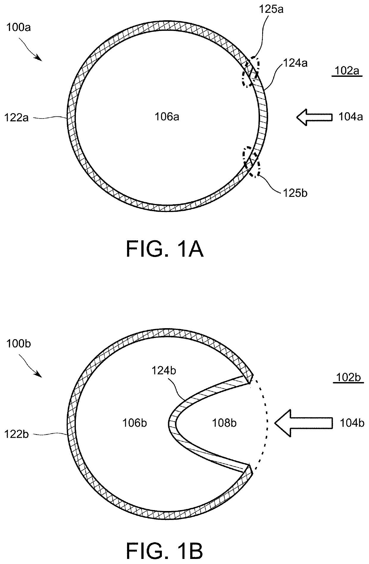
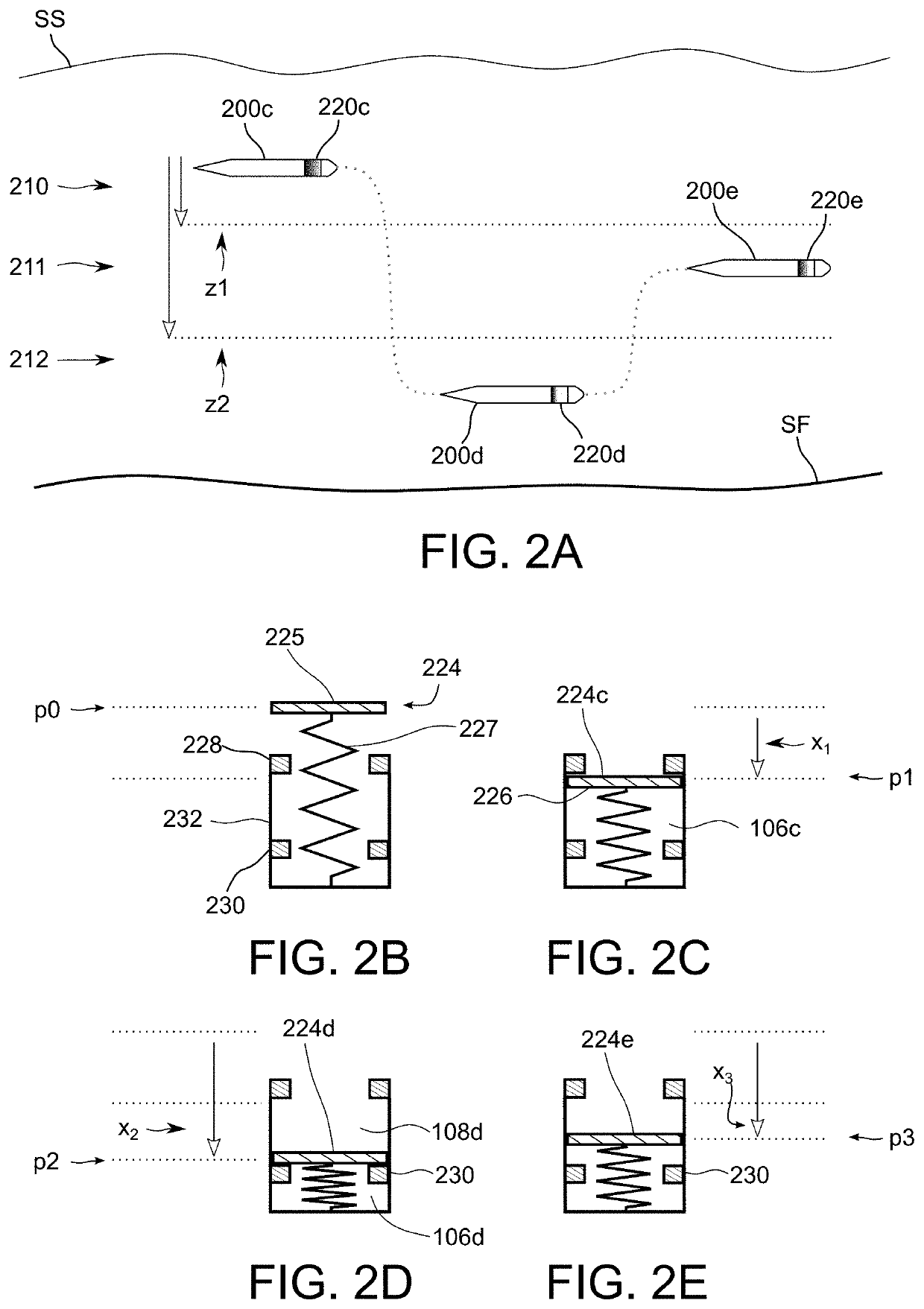
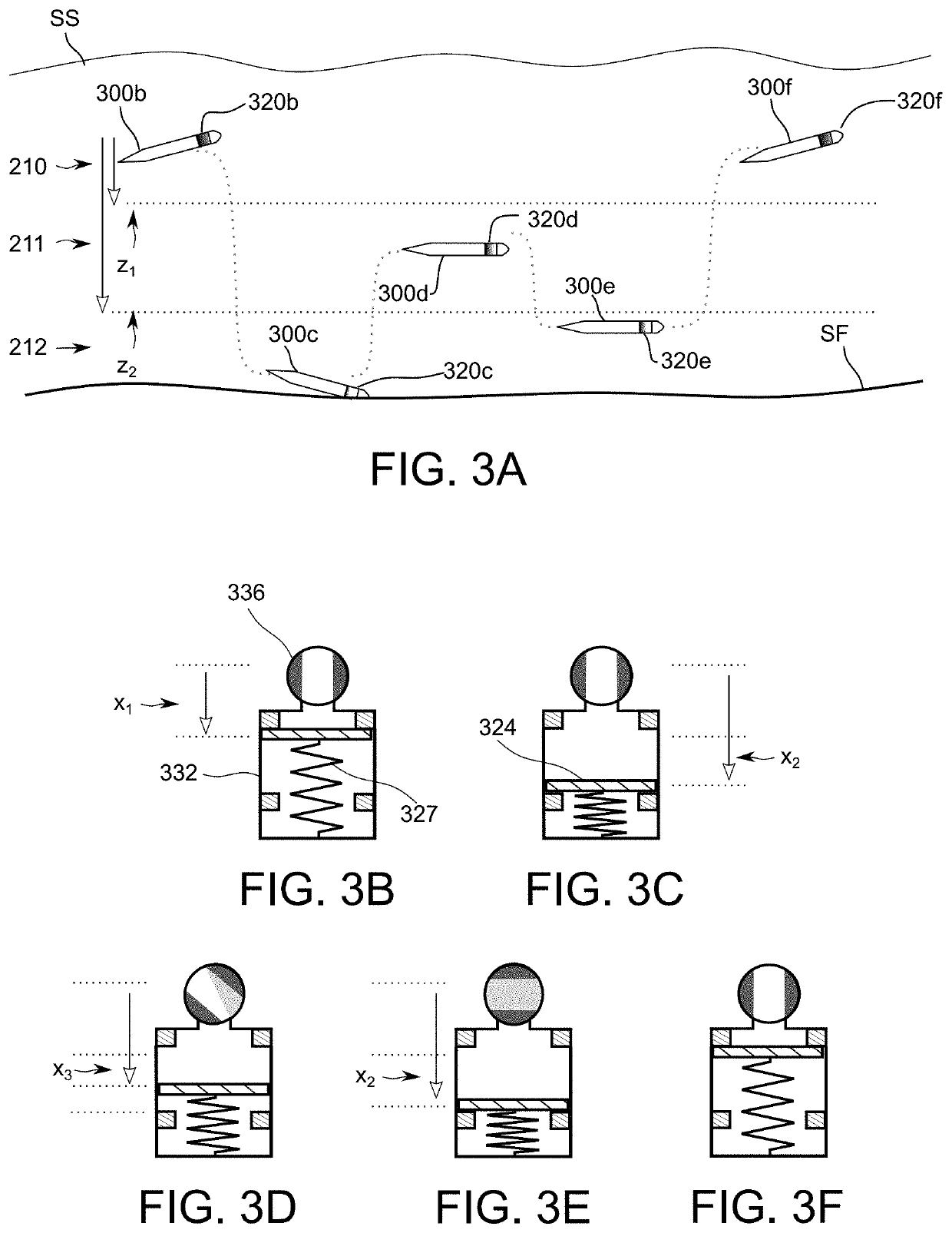
[0206]Another specific embodiment of the instant invention is described herein and illustrated in FIGS. 14A-14C. This embodiment of the present invention is referred to as Passive Variable Ballast (PVB) System 1400a. The PVB is a modification of the passive ballast system described above, comprising a compensator 224 (e.g. a piston), a chamber 232, at least one stop 230, and a working medium WM (e.g. a compressible gas) disposed in, and in almost all cases, filling (i.e. expanding to fill) chamber 232. The chamber 232 is further divided into at least two sections, divided by the stops 230 into a fixed section FS and a variable section VS. Fixed section FS and variable section VS sections are separated physically by stops 230 insomuch as the compensator 224 may not move into the fixed section FS section. The two sections are connected such that the working medium WM inside chamber 232 may expand into both sections. As disclosed elsewhere herein, compens...


PUM


Abstract

A passive ballast device, system and method of using same, configured for use with a submersible vehicle in a liquid environment, including a chamber having at least one rigid wall to define at least a portion of a chamber volume, and a passively movable compensator having at least first and second surfaces, the first surface configured to be exposed to the liquid environment, the second surface excluded from the liquid environment, and forming, together with the at least one wall of the chamber, a fluid-tight seal to establish the remainder of the chamber volume, to exclude the liquid environment from the chamber volume and configured to adjust the chamber volume to at least a first chamber volume and a second chamber volume. The chamber volume is configured to establish at least a first buoyancy and second buoyancy, the compensator is configured to respond to a change in environmental pressure within the liquid environment, and the compensator is passively moved by the change in environmental pressure to change the first chamber volume to the second chamber volume, thereby changing from the first buoyancy to the second buoyancy.

Description

CROSS-REFERENCE TO RELATED APPLICATION[0001]This application claims priority to U.S. application Ser. No. 16 / 572,808 filed on 16 Oct. 2018, which claims priority to U.S. Provisional Application Nos. 62 / 572,808 filed 16 Oct. 2017 and 62 / 722,688 filed 24 Aug. 2018. The entire contents of each of the above-mentioned applications are incorporated here by reference.FIELD OF THE INVENTION[0002]This invention relates to ballasting systems for submergible vehicles and, more particularly, to passively-adjustable ballast and depth control systems for stationary or in-motion submerged vehicles within a liquid body.BACKGROUND OF THE INVENTION[0003]Autonomous underwater vehicles (AUVs) are inherently energy-limited because they must carry their own batteries or other power source. They are also typically ballasted to be positively buoyant. While positive buoyancy is convenient for floating on the surface and obtaining a GPS fix, or as a fail-safe in the event of a system failure, positive buoyan...

Claims


Application Information

Patent Timeline
Patent Type & Authority Patents(United States)
IPC IPC(8): B63G8/24B63G8/39G05D1/00G05D1/04B63G8/00
CPCB63G8/24B63G8/39G05D1/0016G05D1/0022G05D1/048B63G2008/005B63G8/22B63G2008/004G05D1/0692
Inventor KAELI, JEFFREYLITTLEFIELD, ROBIN
Owner WOODS HOLE OCEANOGRAPHIC INSTITUTION
Why Eureka
Try Eureka