Journal bearing

a technology of journal bearings and bearings, applied in the field of journal bearings, can solve the problems of increasing the loss of bearings and prone to oversupply of oil, and achieve the effects of reducing the amount of lubricating oil, and reducing the amount of oil

Active Publication Date: 2012-02-28
MITSUBISHI HEAVY IND LTD
View PDF15 Cites 20 Cited by
  • Summary
  • Abstract
  • Description
  • Claims
  • Application Information

AI Technical Summary

Benefits of technology

[0008]The present invention was made to address such a situation, with an object of providing a journal bearing capable of reducing the amount of the lubricating oil released (supplied) between the outer circumferential surface of the rotation shaft and the inner circumferential surfaces of the pads, so as to reduce the churning loss between the outer circumferential surface of the rotation shaft and the inner circumferential surfaces of the pads, and to reduce the bearing loss.
[0019]The present invention can offer an effect of reducing the amount of lubricating oil released (supplied) between the outer circumferential surface of the rotation shaft and the inner circumferential surfaces of the pads, so as to reduce the churning loss between the outer circumferential surface of the rotation shaft and the inner circumferential surfaces of the pads, and to reduce the bearing loss.

Problems solved by technology

However, in such a journal bearing, since lubricating oil is released (supplied) from the oiling nozzles attached to the upper half of the carrier ring which does not receive any load (which is not loaded), the oil is prone to be oversupplied.
This leads to a problem of an increase in the churning loss between the outer circumferential surface of the rotor shaft (rotation shaft) and the inner circumferential surfaces of the pads, causing an increase in the bearing loss.

Method used


Image

  • Journal bearing
  • Journal bearing
  • Journal bearing

Examples


Embodiment Construction

[0023]Hereafter is a description of one embodiment of a journal bearing according to the present invention, with reference to FIG. 1 through FIG. 3.

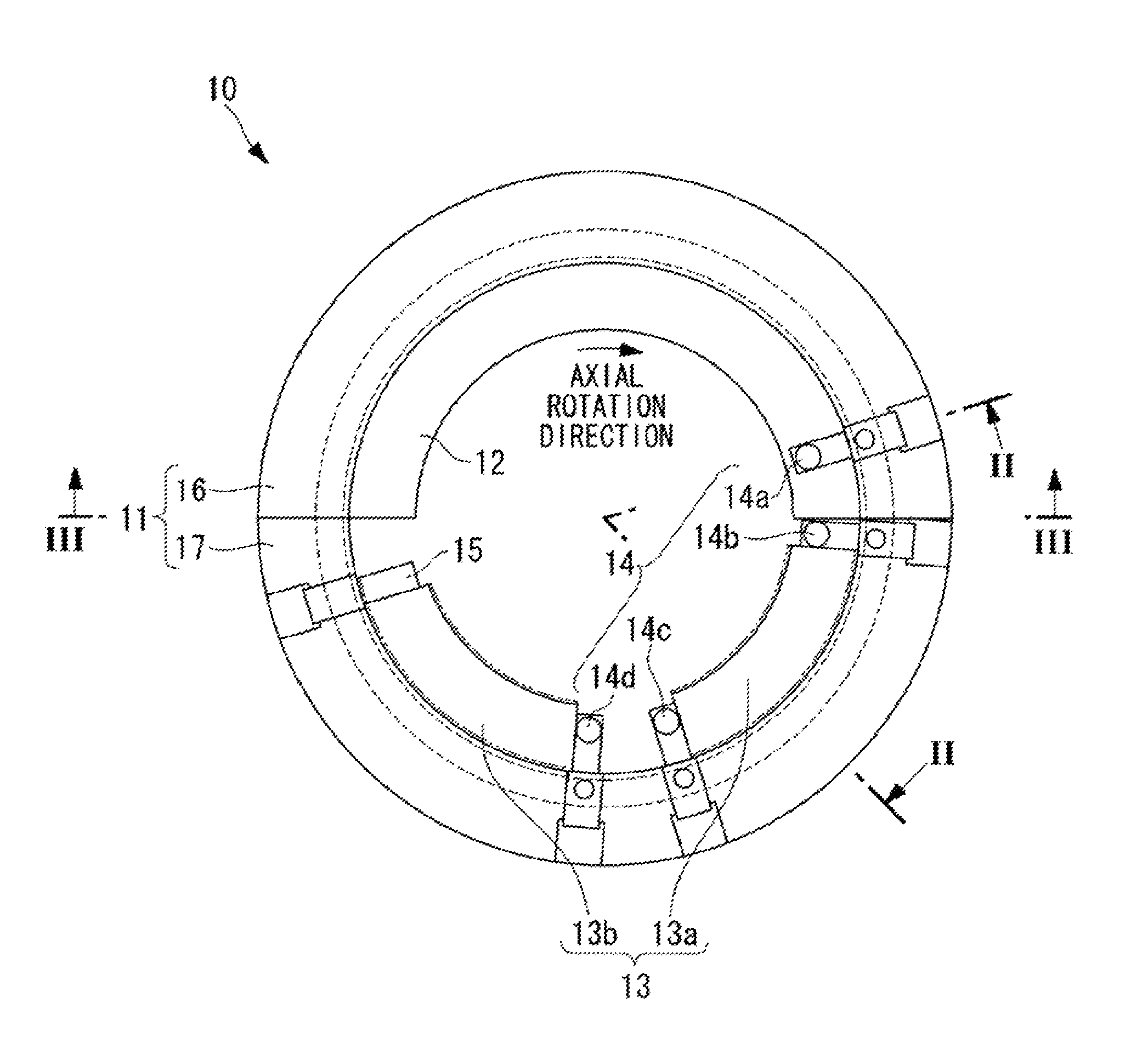
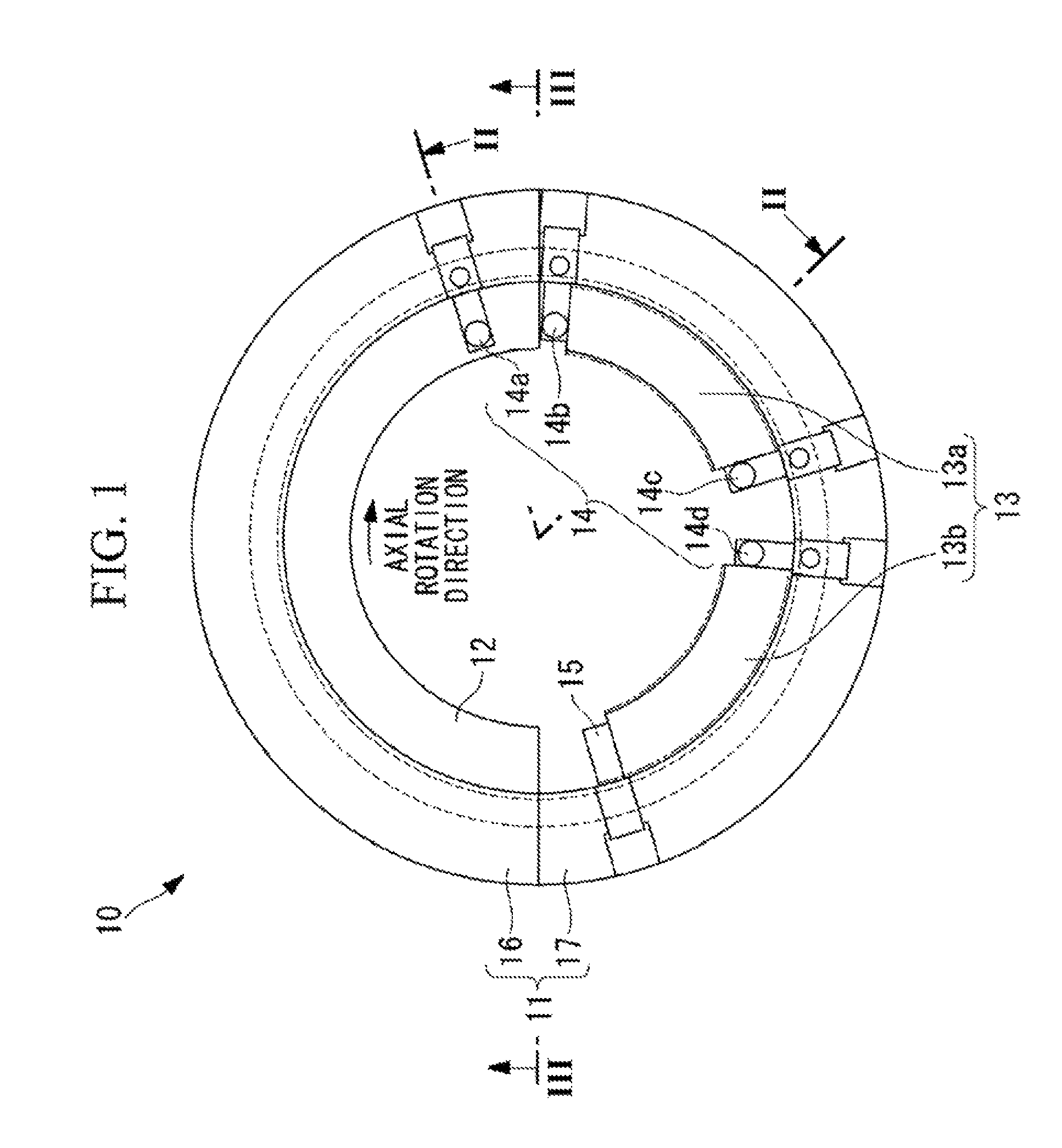
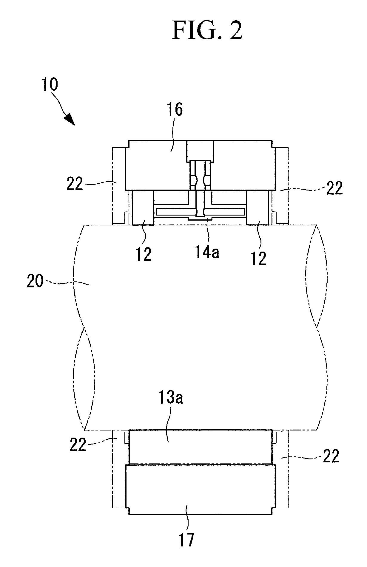
[0024]FIG. 1 is a front view of the journal bearing according to this embodiment. FIG. 2 is a cross sectional view taken along the line II-II of FIG. 1. FIG. 3 is a cross sectional view taken along the line III-III of FIG. 1.

[0025]As shown in FIG. 1, the journal bearing 10 comprises a carrier ring 11, guide metals 12, a plurality of (two in this embodiment) pads 13, a plurality of (four in this embodiment) oiling nozzles (pad stops) 14, and a first pad stop 15, as main components.

[0026]The carrier ring 11 comprises an upper half-carrier ring 16 and a lower half-carrier ring 17. The upper half-carrier ring 16 and the lower half-carrier ring 17 are connected via joint bolts (not shown).

[0027]As shown in FIG. 2, two guide metals 12 are aligned in the axial direction. As shown in FIG. 1 and FIG. 2, these guide metals 12 are secured to the ra...


PUM


Abstract

A journal bearing has a plurality of pad stops which include a first pad stop located at a most forward position in the rotation direction of the rotation shaft, and the pad stops other than the first pad stop function as oiling nozzles for releasing lubricating oil between the outer circumferential surface of the rotation shaft and the inner circumferential surfaces of the pads.

Description

BACKGROUND OF THE INVENTION[0001]1. Field of the Invention[0002]The present invention relates to a journal bearing for use in rotating machines such as a steam turbine, a gas turbine, a blower, and a compressor.[0003]This application is based on Japanese Patent Application No. 2009-047355, the content of which is incorporated herein by reference.[0004]2. Description of Related Art[0005]A journal bearing disclosed in Japanese Unexamined Utility Model Application, Publication No. Sho 63-132114 is known as an example of a journal bearing for use in rotating machines such as a steam turbine, a gas turbine, a blower, and a compressor.BRIEF SUMMARY OF THE INVENTION[0006]Recently, a journal bearing has been proposed in which a plurality of (for example, four) pads are arranged radially inside a carrier ring along the circumferential direction (more specifically, a plurality of (for example, two) pads are arranged radially inside an upper half of the carrier ring (upper half of the mainfram...

Claims


Application Information

Patent Timeline
Patent Type & Authority Patents(United States)
IPC IPC(8): F16C32/06F16C13/00F16N1/00
CPCF16C17/03F16C33/08F16C33/1025F16C33/1085F16C2360/23F16C32/067F16C32/0685F16C33/108F16C2360/00F16C33/10
Inventor WAKI, YUICHIRONAKANO, TAKASHIYAMASUE, SHINGOTANAKA, SHINGOKAIKOGI, TAKAAKIHIROKAWA, KAZUHARU
Owner MITSUBISHI HEAVY IND LTD
Why Eureka
Try Eureka