Connector for large power transmission

a technology for connecting devices and power transmission, applied in the direction of coupling device connection, coupling parts engagement/disengagement, incorrect coupling prevention, etc., can solve problems such as failure of electrical connection

Inactive Publication Date: 2012-02-28
HITACHI CABLE
View PDF21 Cites 18 Cited by
  • Summary
  • Abstract
  • Description
  • Claims
  • Application Information

AI Technical Summary

Benefits of technology

[0012]Therefore, it is an object of the invention to provide a connector that includes a connection structure with plural first connecting terminals, plural second connecting terminals and plural insulation plates arranged in a stacked state and is unlikely to cause an electrical connection failure by constructing such that its contacts cannot be easily fastened together by its connecting member except when the connecting terminals are mutually at a predetermined position.
[0032]According to one embodiment of the invention, a connector is constructed such that the fastening operation of a connecting member by a lever mechanism is not permitted when the fitting of connector parts is incomplete, and the fastening operation of the connecting member by the lever mechanism is permitted only when the fitting of the connector parts is completed. Thereby, the connection failure between the first connecting terminals and the second connecting terminals can be prevented.

Problems solved by technology

However, the construction as disclosed in JP patent 4037199 may cause a problem described below.
Because of this, failure in electrical connection may be caused.

Method used


Image

  • Connector for large power transmission
  • Connector for large power transmission
  • Connector for large power transmission

Examples


Embodiment Construction

[0057]The preferred embodiments according to the invention will be explained below referring to the drawings.

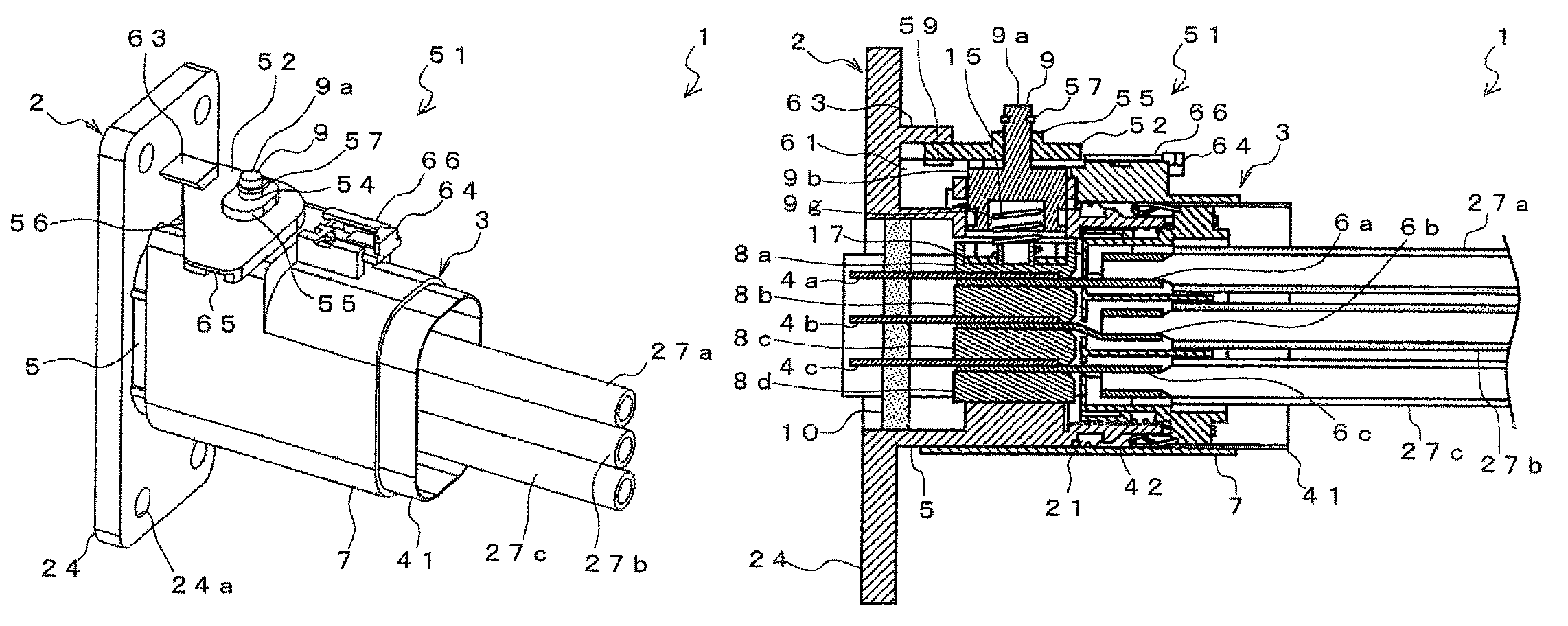
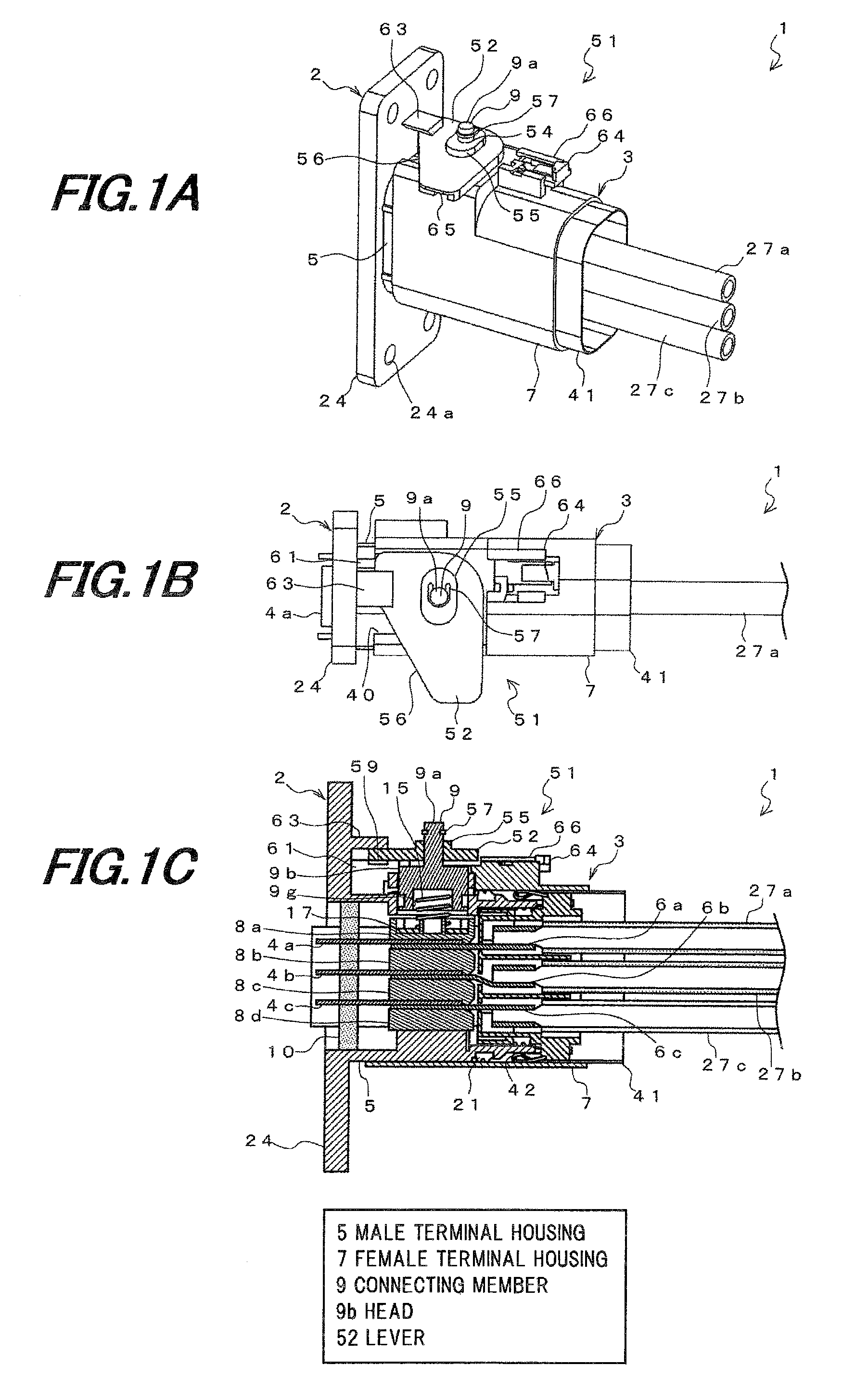
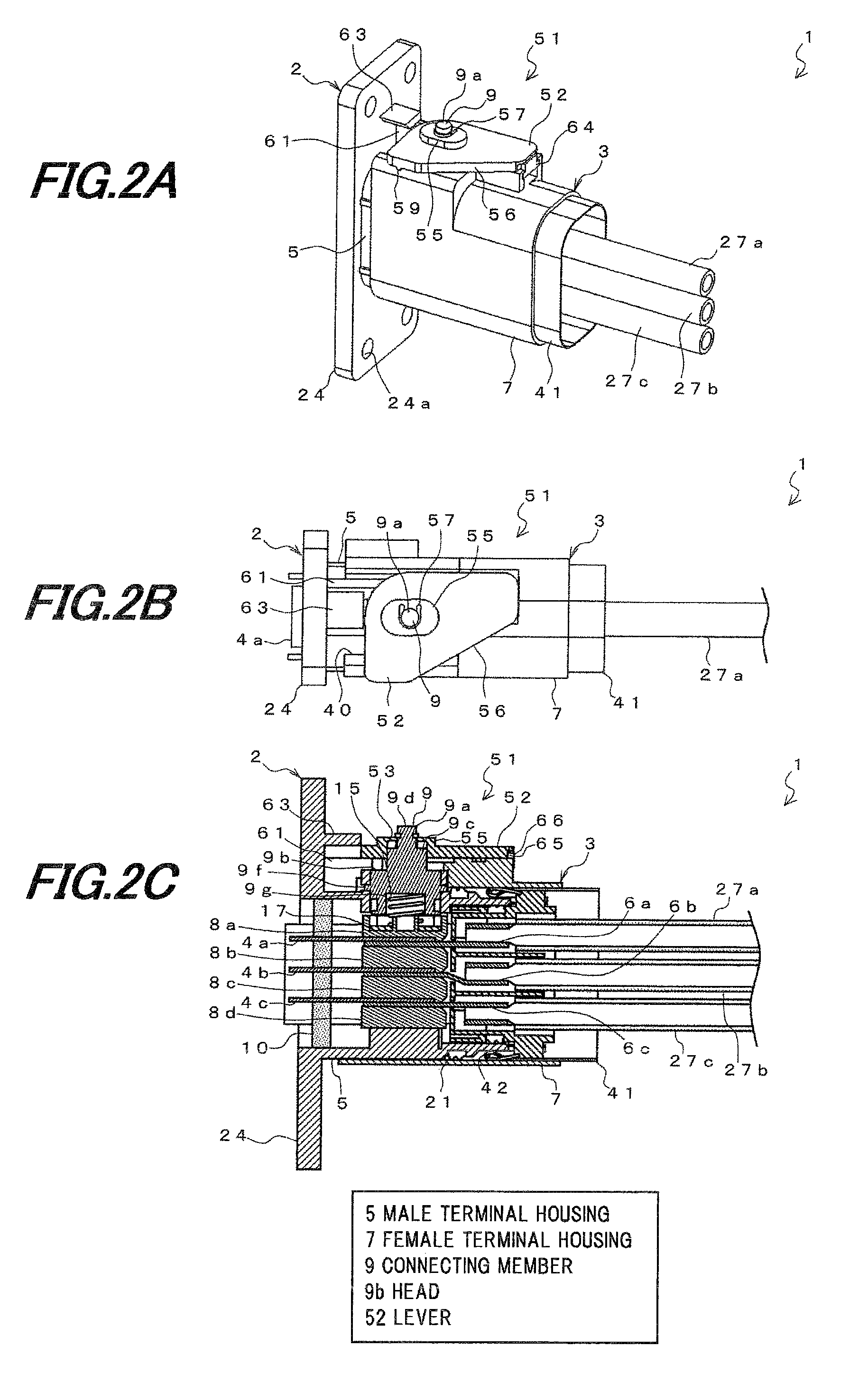
[0058]FIG. 1A is a perspective view schematically showing a connector when a lever is located at a releasing position according to one embodiment of the invention, FIG. 1B is a top view schematically showing a connector when a lever is located at a releasing position according to one embodiment of the invention, FIG. 1C is a cross-sectional side view schematically showing a connector when a lever is located at a releasing position according to one embodiment of the invention, FIG. 2A is a perspective view schematically showing a connector when a lever is located at a fixing position in FIG. 1A, FIG. 2B is a top view schematically showing a connector when a lever is located at a fixing position in FIG. 1B, and FIG. 2C is a cross-sectional side view schematically showing a connector when a lever is located at a fixing position in FIG. 1C.

[0059]As shown in FIGS. 1A to 1C and FIG...


PUM


Abstract

A connector includes a male terminal housing with a plurality of first connecting terminals aligned and accommodated therein, a female terminal housing with a plurality of second connecting terminals aligned and accommodated therein, a plurality of isolating plates aligned and accommodated in the male terminal housing, a connecting member, and a lever mechanism including a lever to rotate a head of the connecting member so as to press the head of the connecting member against the adjacent one of the plurality of insulation plates. The lever mechanism further includes an operation permitting means that permits the connecting member to collectively fix the plurality of first connecting terminals and the plurality of second connecting terminals at the contacts, when the male terminal housing and the female terminal housing are in a predetermined fitting state.

Description

[0001]The present application is based on Japanese patent application No. 2010-020687 filed on Feb. 1, 2010, the entire contents of which are incorporated herein by reference.BACKGROUND OF THE INVENTION[0002]1. Field of the Invention[0003]The present invention relates to a connection structure, for use in eco-friendly cars, such as hybrid vehicles, electric vehicles and the like, and in particular, for being capable of use for a portion to connect a power harness, which is used for large power transmission.[0004]2. Description of the Related Art[0005]In hybrid vehicles, electric vehicles and the like which have remarkably developed in recent years, a power harness, which is used for large power transmission for connection between devices, has at its one end a connector, which consists of two separate portions: a male connector portion with a male terminal and a first terminal housing accommodating that male terminal, and a female connector portion with a female terminal connected wi...

Claims


Application Information

Patent Timeline
Patent Type & Authority Patents(United States)
IPC IPC(8): H01R13/62H01R13/64
CPCH01R13/62H01R13/62933
Inventor SUZUKI, SACHIOTAKEHARA, HIDEAKIFUKUDA, KUNIHIROKATAOKA, YUTA
Owner HITACHI CABLE
Why Eureka
Try Eureka