Method of fabricating a chromium nitride coated separator

a technology of chromium nitride and separator, which is applied in the direction of cell components, final product manufacturing, sustainable manufacturing/processing, etc., can solve the problems of limited wide use of fuel cells in the industry, and high price of separator

Active Publication Date: 2012-02-28
SEOUL NAT UNIV R&DB FOUND
View PDF9 Cites 0 Cited by
  • Summary
  • Abstract
  • Description
  • Claims
  • Application Information

AI Technical Summary

Benefits of technology

[0011]The present invention provides a metallic separator for a fuel cell, which costs less and smaller thickness compared to a graphite separator.
[0020]The method may further include rapidly cooling the separator so as not to form CrN compound during the cooling process after nitridization.

Problems solved by technology

However, previously produced fuel cells are very expensive and wide use of them in industry is limited.
However, due to the high cost of the graphite material itself and high processing cost of a plate, the price of the separator is very high.
In addition, since the graphite separator is fragile, it is not easy to process the graphite separator to a thickness of 4-5 mm or below.
Thus, it is difficult to reduce the size of a fuel cell stack consisting of several tens to several hundreds of unit cells to a desirable dimension.
However, metals can corrode in oxidative environment inside the stack and oxide films that have large electrical resistivity can easily form on the surface of the metallic separator.
Problems such as membrane poisoning or an increase of contact resistance can occur.
Corrosion of metallic separator can cause the formation of defects in the metallic separator and the poisoning of catalyst and electrolyte by the diffusion of metallic ions into the electrolyte membrane.
Such a corrosion problem is the largest obstacle for the application of the metallic separator.
However, the cost of high chromium alloy steel can be very high and the corrosion resistance of the coated layer is not sufficient for fuel cell.

Method used


Image

  • Method of fabricating a chromium nitride coated separator
  • Method of fabricating a chromium nitride coated separator
  • Method of fabricating a chromium nitride coated separator

Examples


Embodiment Construction

[0031]The present invention will now be described in more detail with the reference to the accompanying drawings, in which exemplary embodiments of the invention are shown.

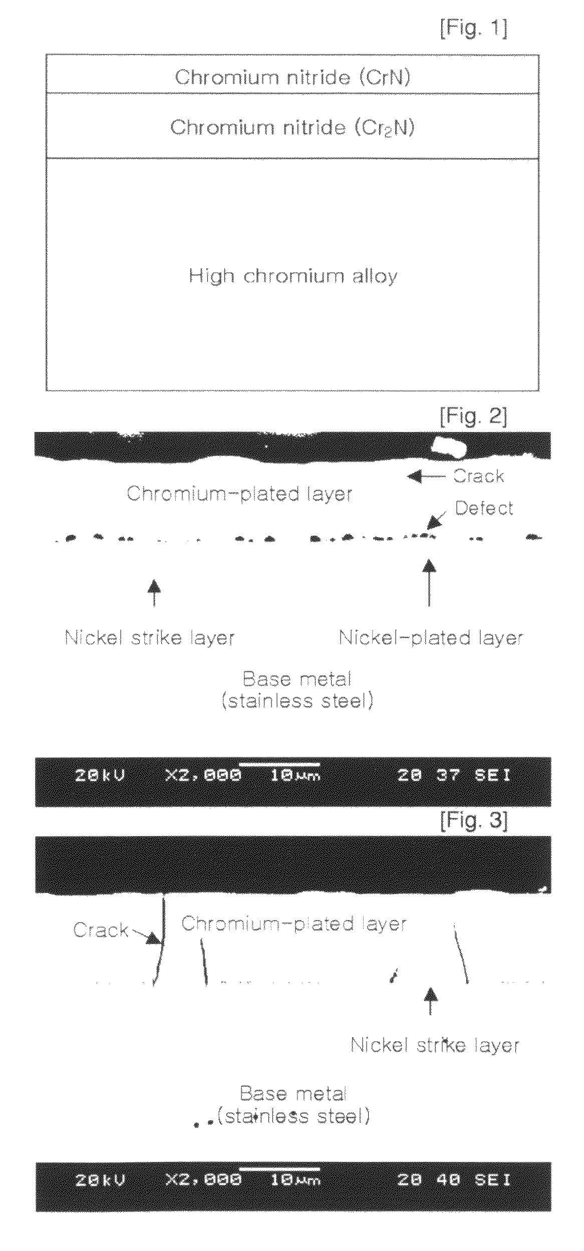
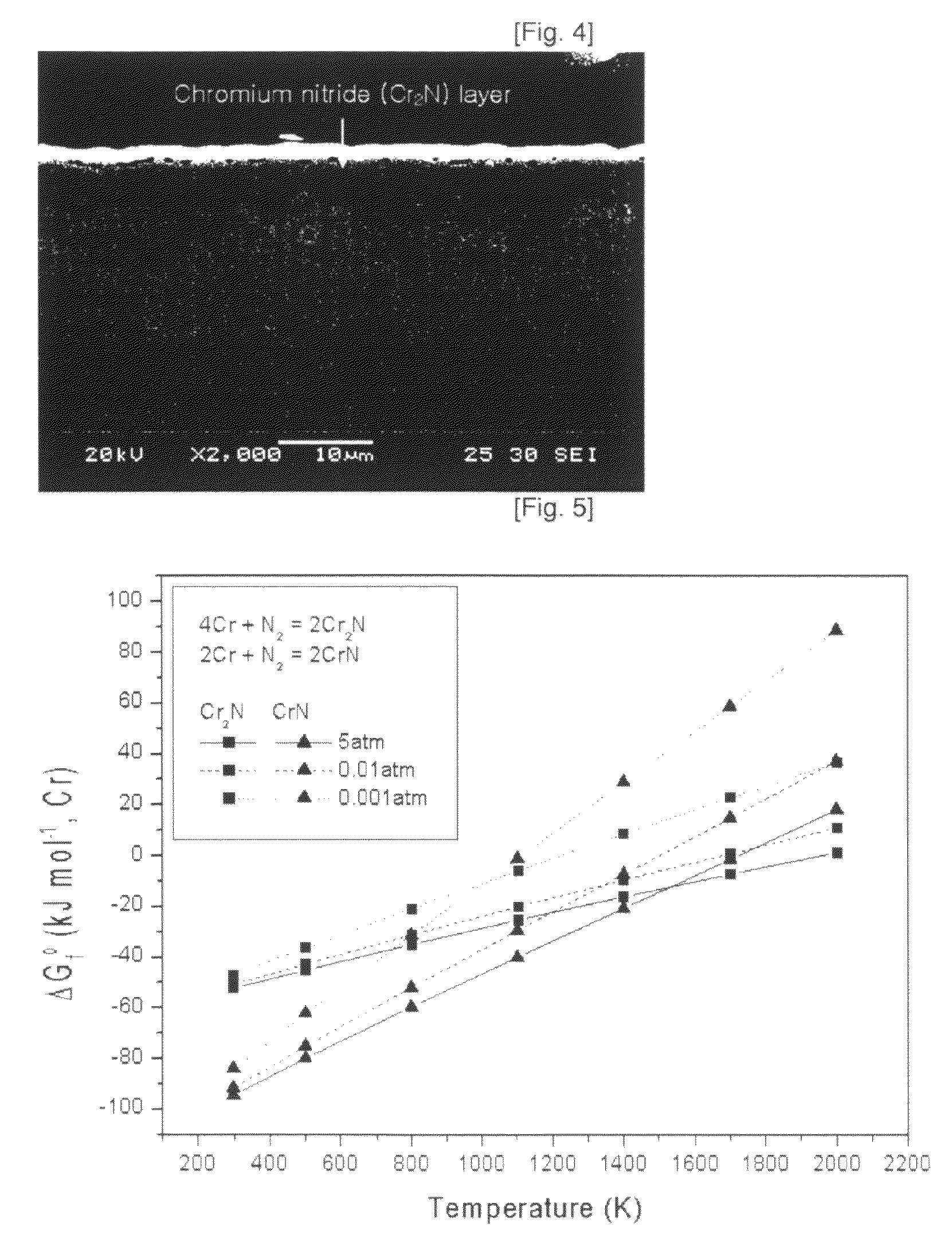
[0032]FIG. 2 illustrates a photographic image showing a cross-section of a separator, in which conventional nickel strike, nickel and chromium are sequentially plated on the surface of stainless steel. FIG. 3 illustrates a photographic image showing a cross-section of a separator in which nickel strike and chromium are sequentially plated on the surface of stainless steel according to the present invention. FIG. 4 illustrates a photographic image showing a cross-section of a separator, in which chromium was plated and nitrided on the surface of stainless steel.

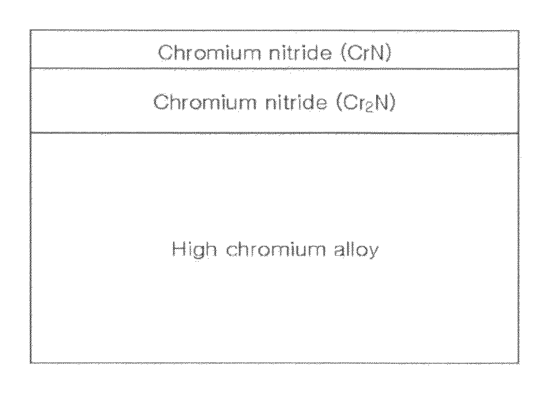
[0033]A metallic separator for a fuel cell according to the present invention has a structure in which a chromium nitride layer is formed on the surface of a chromium plated base metal. In order to form such a chromium nitride layer, firstly, chromium is pla...


PUM

PropertyMeasurementUnit
partial pressureaaaaaaaaaa
temperatureaaaaaaaaaa
thicknessaaaaaaaaaa

Abstract

Provided are a metallic separator for fuel cell in which a Cr2N layer is formed on the surface of base metals, and a method of fabricating the metallic separator or fuel cell. The method comprises: plating chromium layer on the surface of the base metal; and forming a Cr2N layer by nitriding the chromium-plated layer in properly selected nitriding conditions. Only the Cr2N layer, which has lower electrical resistivity than CrN, is selectively fabricated on the surface of the base metal. The interfacial contact resistance of the separator is reduced and the efficiency of the fuel cell can be improved. In addition, since a low-priced general metals or alloys such as stainless steels, carbon steels, alloy steels or even nonferrous alloys can be used as the base metal, the cost of the fabrication of metallic separator can be significantly reduced. The thickness of the separator can be made as small as to 0.2 mm, the weight and total thickness of a fuel cell stack can be significantly reduced.

Description

TECHNICAL FIELD[0001]The present invention relates to a separator for a fuel cell, and more particularly, to a metallic separator for a fuel cell in which chromium nitride layer is fabricated on the surface of a metallic base material, and a method to fabricate the same.BACKGROUND ART[0002]In these days, the importance of the development for fuel cells, which use hydrogen for power generation, is on the increase. Use of fuel cell can not only replace the depleting fossil fuels but also prevents environmental woes such as global warming caused by excessive generation of carbon dioxide. Fuel cells also have various advantages to satisfy the environmental and technical demands. Fuel cells directly convert a chemical energy into an electric energy using hydrogen as a fuel. Because energy efficiency is high and only water is the reaction product as an exhaust material, fuel cell technology is an eco-friendly energy technology.[0003]The operating mechanism of a fuel cell starts from produ...

Claims


Application Information

Patent Timeline
Patent Type & Authority Patents(United States)
IPC IPC(8): H01M2/32H01M8/02H01M50/571
CPCH01M8/0204H01M8/0208H01M8/021H01M8/0228Y02E60/50Y02P70/50H01M8/02
Inventor NAM, DAE GEUNLEE, HU CHUL
Owner SEOUL NAT UNIV R&DB FOUND
Why Eureka
Try Eureka