
Device for receiving and dispensing liquids

a technology for liquids and devices, applied in liquid transferring devices, laboratory glassware, instruments, etc., can solve the problems of large floor space, large number of staff for programming, operating and maintenance, and large number of necessary pipetting steps that cannot be dealt with with conventional manual 8 or 12 channel pipettes

Active Publication Date: 2014-04-01
STEINBRENNER BERND +1
View PDF23 Cites 3 Cited by
  • Summary
  • Abstract
  • Description
  • Claims
  • Application Information

AI Technical Summary

Benefits of technology

The invention is a device that allows for a large number of parallel pipetting processes to be performed for high throughput work without requiring a great investment. The device is significantly less expensive and has a lower running cost compared to automats. Additionally, the device can have a disposable latch-like intermediate stop which can align plates in parallel and allow for the simultaneous dispensing of liquid to several working plates. This simplifies processing and ensures consistent results. Overall, the invention provides an inexpensive, efficient and effective solution for high throughput work.

Problems solved by technology

The large number of necessary pipetting steps can practically no longer be dealt with using conventional manual 8 or 12 channel pipettes.
These devices are, however, extremely expensive, require a large amount of floor space and a large number of staff for programming, operating and maintenance.
A spindle drive of this type, having the required rapid and precise simultaneous spindle speed, is inappropriate for a pipetting system which is operated manually or with a simple drive, since either the mechanical devices or the control and drive are excessively complex or expensive.
However, this mechanism of prior art is deficient with regard to handling such very precise volumes during pipetting, since these guidances cannot guarantee absolute parallelism and thereby exactly identical volumes of the liquid to be pipetted, compared to the controlled spindle drives of the above-mentioned automatic units, wherein excessive expense to ensure exact plate guidance would, in turn, be uneconomical.
This problem increases with the number of piston-cylinder units and thereby with the size of the plates, such that these guidances can simultaneously operate either only a few piston-cylinder units or volume accuracy is not possible.

Method used


Image

  • Device for receiving and dispensing liquids
  • Device for receiving and dispensing liquids
  • Device for receiving and dispensing liquids

Examples


Embodiment Construction

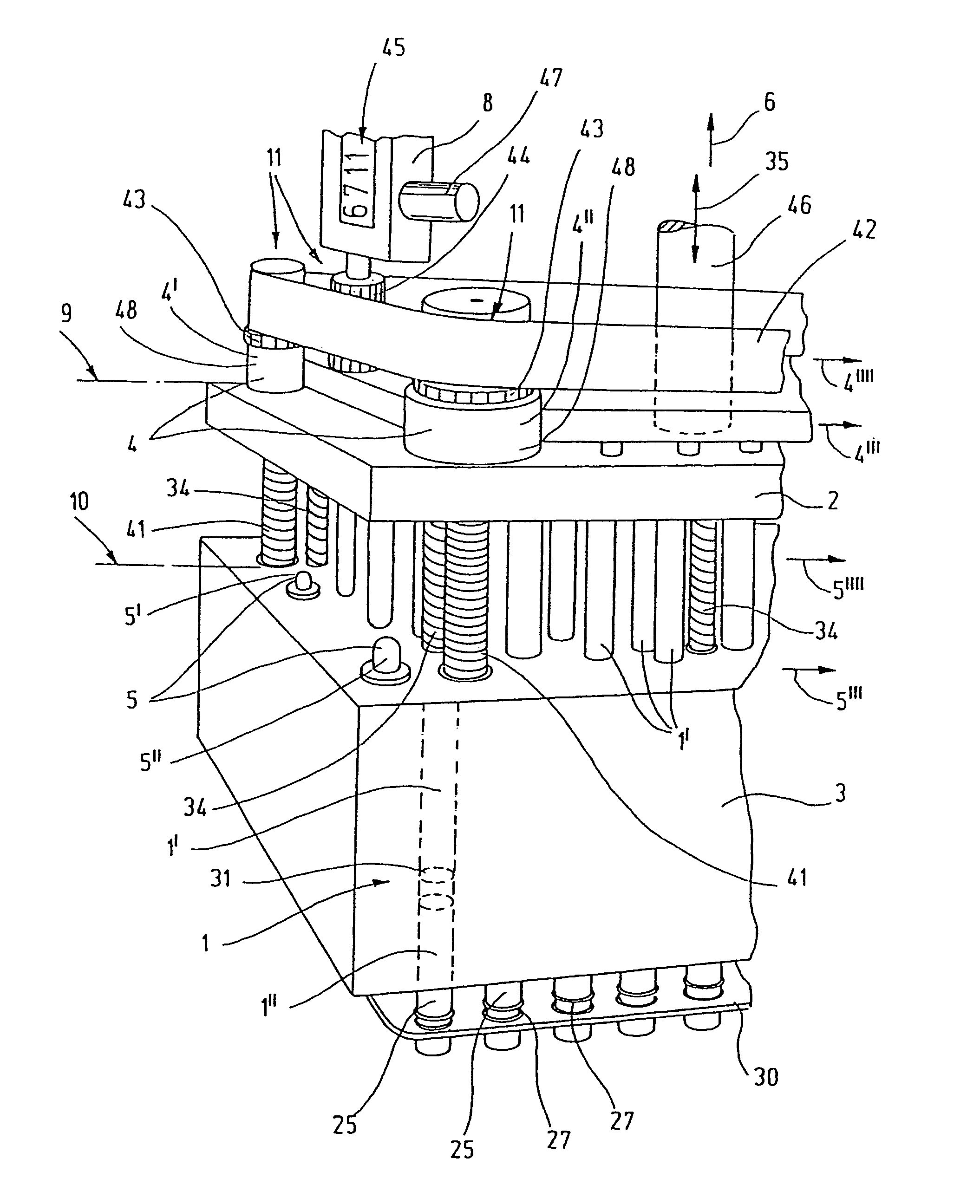
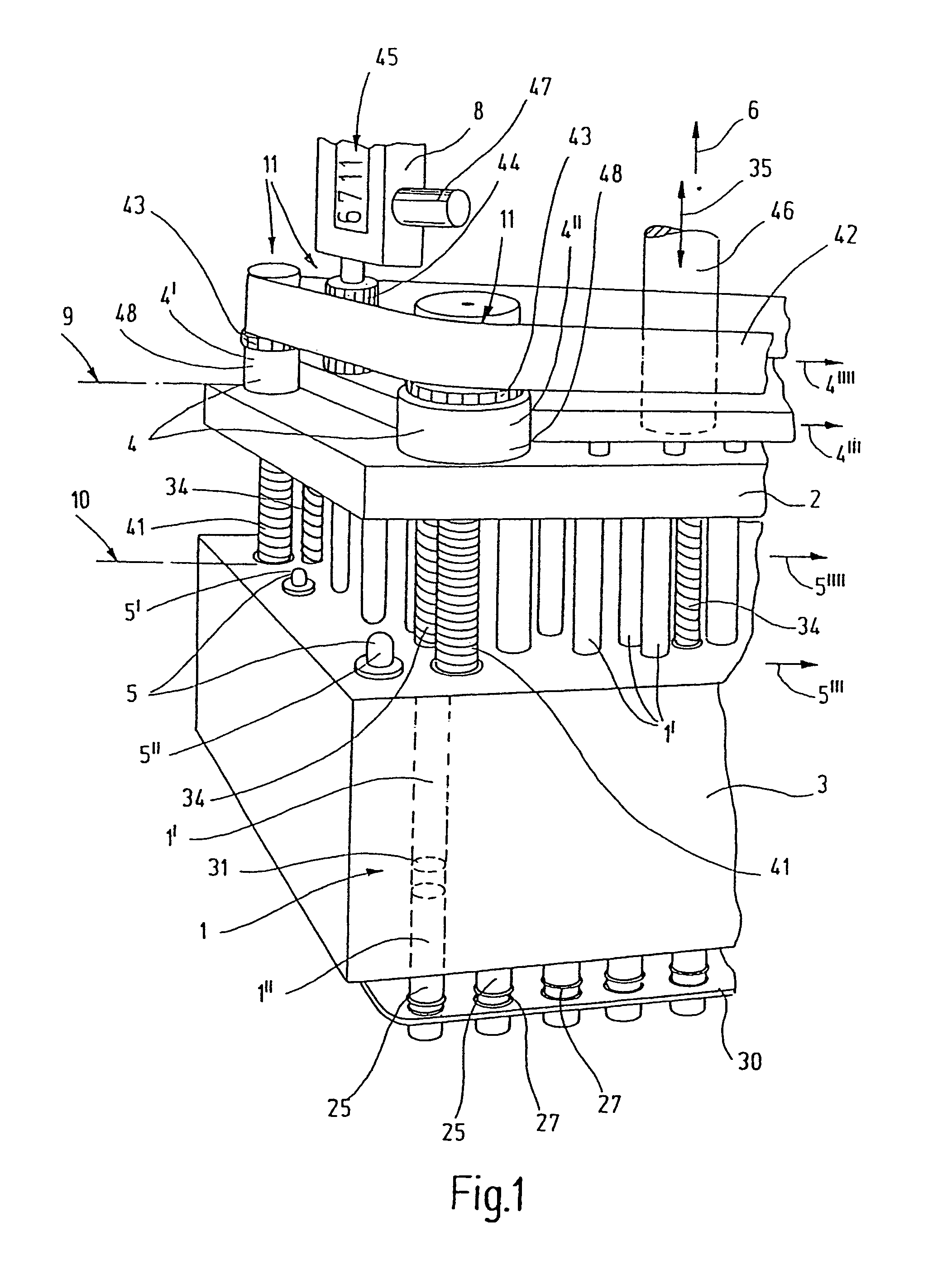
[0038]FIG. 1 shows the functional structure of an embodiment of the inventive device. Piston-cylinder units 1 are arranged like a grid, such that the piston 1′ is located on a piston plate 2 and the cylinder 1″ on a cylinder plate 3. The cylinders 1″ of the embodiment shown are formed by providing the cylinder plate 3 with corresponding bores. In this fashion, a suction motion is generated by an upward motion of the piston plate 2 and a discharge motion is generated by a downward motion of the piston plate 2. In order to seal the pistons 1′ tightly with respect to the cylinders 1″, each of them may be provided with a sealing ring 31. In the illustration, a piston-cylinder unit 1 with piston 1′, sealing ring 31 and cylinder 1″ is shown in dashed lines as an example. In fact, a plurality of such units 1 are provided in a grid-shaped arrangement. In correspondence with conventional working plates 16, a grid of 96 piston-cylinder units 1 may be selected to handle the working positions o...


PUM

PropertyMeasurementUnit
volumeaaaaaaaaaa
volumesaaaaaaaaaa
volumeaaaaaaaaaa

Abstract

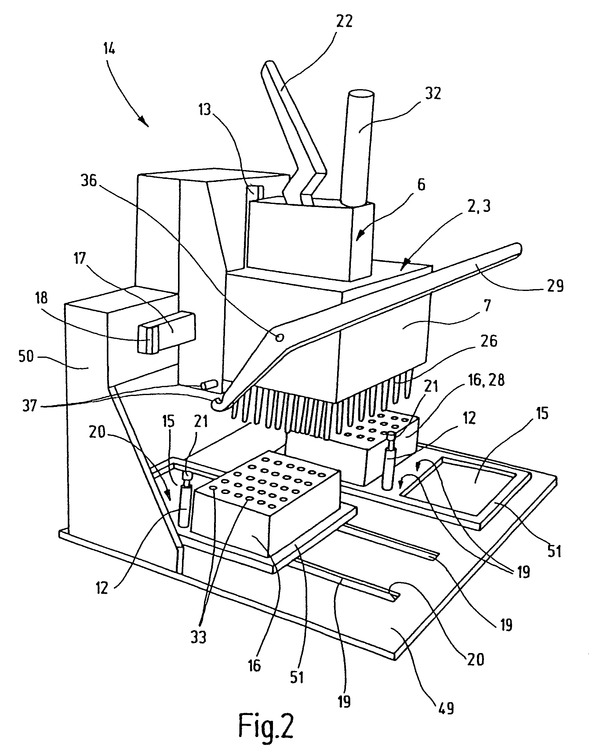
A device for receiving and dispensing liquids has a plurality of piston-cylinder units (1, 1′, 1″) which are respectively arranged on a piston plate (2) and a cylinder plate (3). The liquid is received and dispensed by displacing the pistons (1′) in the cylinders (1″) by changing the distance between the plates (2, 3), perpendicularly to the plate planes, by means of a drive mechanism (6) and a plate guiding system. The volume can be determined by an upper abutment (4) and a lower abutment (5), at least one of said abutments being regulatable by a regulating means (8). The device is suitable for handling precise volumes of a larger number of piston-cylinder units (1, 1′, 1″) in a technically simple manner. To this end, the same receiving and dispensing volumes of the piston-cylinder units (1, 1′, 1″) are ensured with low requirements in terms of the surface parallelism of the plate planes during the movement in the plate guiding device, by structuring and arranging the abutments (4, 5) in such a way that the parallelism of the plates (2, 3) is obtained in the upper (9) and lower (10) abutment positions.

Description

[0001]This application is a continuation of Ser. No. 11 / 578,826 filed Oct. 19, 2006 now abandoned as the national stage of PCT / EP2005 / 004694 filed on Apr. 30, 2005 and claims Paris Convention priority of DE 10 2004 023 517.1 filed May 10, 2004 and DE 10 2004 023 690.9 filed May 13, 2004 the entire disclosures of which are hereby incorporated by reference.BACKGROUND OF THE INVENTION[0002]The invention concerns a device for receiving and dispensing liquids, with a plurality of piston-cylinder units which are disposed on a piston plate and a cylinder plate, respectively, wherein the liquid is received and dispensed by displacing the pistons in the cylinders by changing the distance between the plates using a drive mechanism and a plate guidance, perpendicularly to the plate planes, wherein the volume can be determined by an upper and a lower stop, at least one of which can be adjusted using at least one adjusting means.[0003]In modern biological research, high-throughput methods are in...

Claims


Application Information

Patent Timeline
Patent Type & Authority Patents(United States)
IPC IPC(8): B67D99/00B01L3/02G01N35/10
CPCB01L3/02B67D99/00G01N35/10B01L3/0293B01L2300/0861B01L2400/0478B01L2300/0829B01L9/523B01L2200/025B01L2200/0689
Inventor STEINBRENNER, BERNDSTEINBRENNER, ROGER
Owner STEINBRENNER BERND
Learn More