Wheel steering apparatus
a technology of steering apparatus and wheel, which is applied in the direction of couplings, interlocking clutches, gearing, etc., can solve the problems of considerable loss and adverse effects on the steering ability of the vehicl
- Summary
- Abstract
- Description
- Claims
- Application Information
AI Technical Summary
Benefits of technology
Problems solved by technology
Method used
Image
Examples
first embodiment
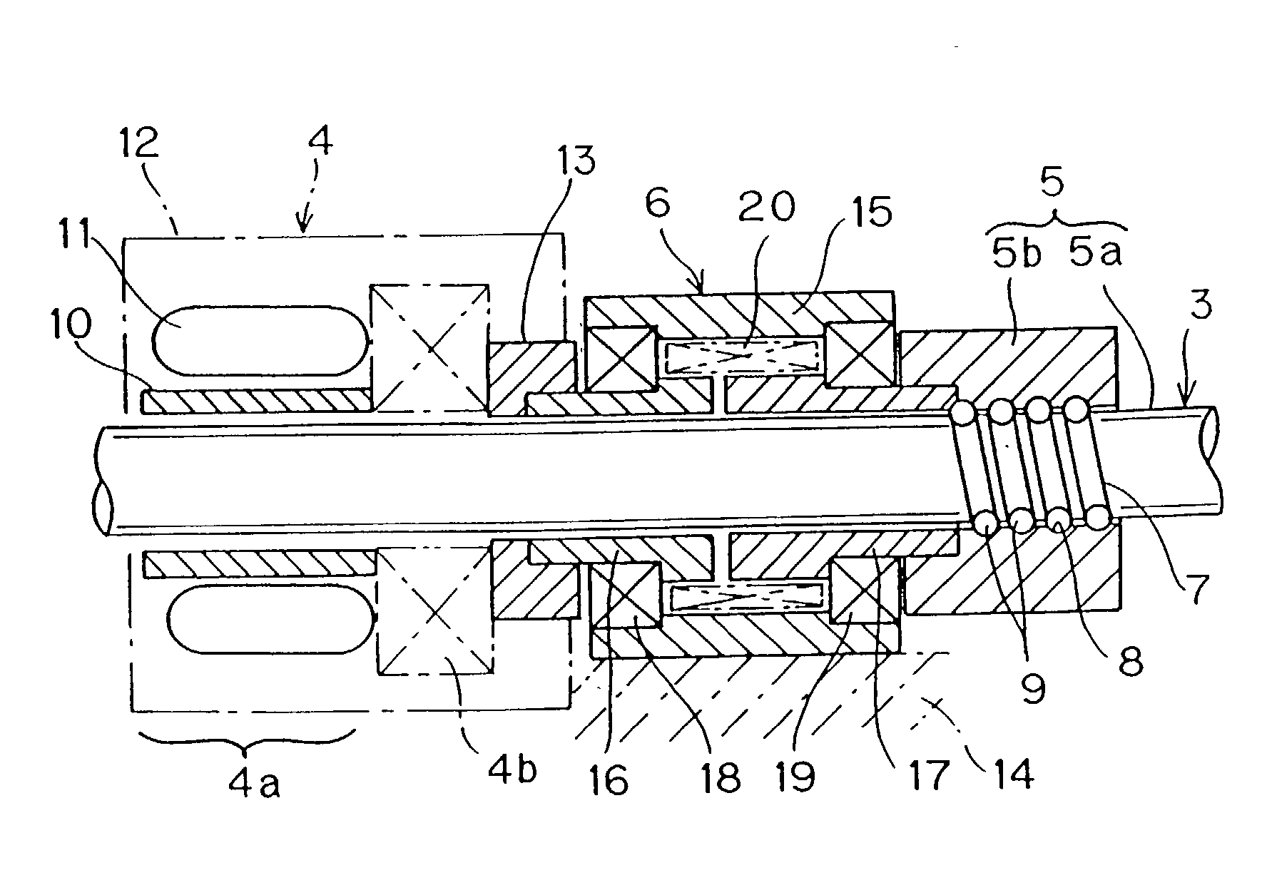
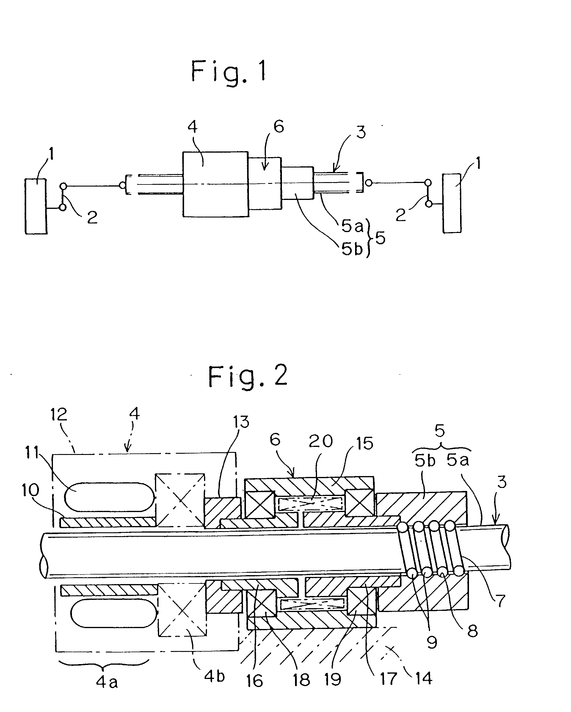
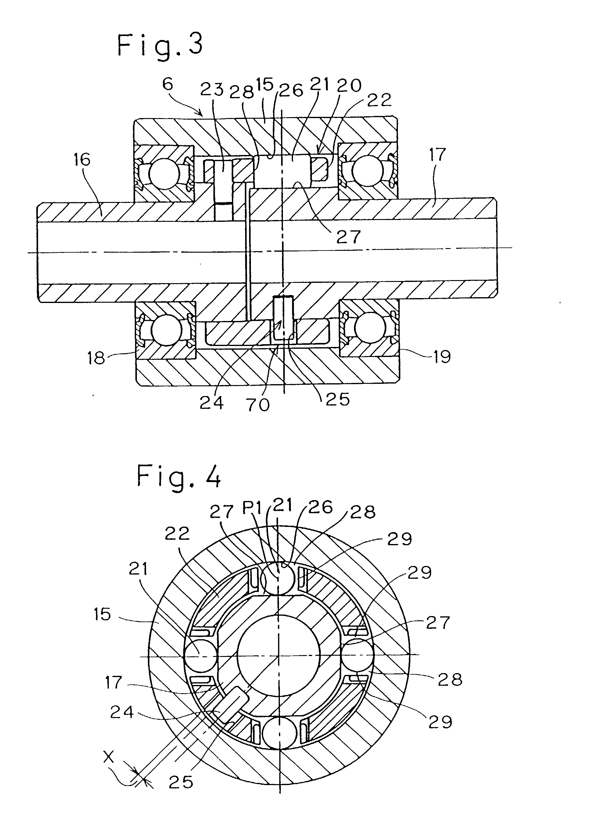
[0064] A third preferred embodiment of the present invention is shown in FIGS. 10 to 13. The wheel steering apparatus according to this embodiment is substantially similar to that shown in and described with reference to FIGS. 1 to 6, except for the following structural features. It is, however, to be noted that even in this embodiment shown in FIGS. 10 to 13, the clutch assembly 6, now identified by 6C, is a two-way clutch assembly of a reverse input limiting type that is, as regards the rotations in opposite directions are concerned, operable to transmit rotation from an input side ring 16C to an output side ring 17C, but to interrupt transmission of rotation from the output side ring 17C to the input side ring 16C.
[0065] More specifically, in the embodiment shown in FIGS. 10 to 13, the output side ring 17C of the clutch assembly 6C and the nut member 5b of the ball screw mechanism 5C are respective integral parts of a one-piece component 80. One axial end portion of the one-piec...
third embodiment
[0072] The clutch assembly 6C of the structure in accordance with the present invention will now be described. This clutch assembly 6C is of a design wherein the retainer 22C applies a rotational input together with the input side ring 16C. So long as no rotation occurs, as shown in FIG. 13A, the engagement elements 21C are biased by the respective elastic member 82 to assume the engaged operative position P2c at the cam face portions 27C, and 27C.sub.2 of the output side ring 17C that serves as an inner race. Since the outer race 15C is fixed to the stationary member 14 which is a stationary system as shown in FIG. 10, an attempt to rotate the output side ring 17C in a clockwise direction shown by the arrow r in FIG. 13A causes one of the paired engagement elements 21C.sub.1, which is positioned on a trailing side with respect to the direction r of rotation of the output side ring 17C as viewed in FIG. 13A, to lock and, accordingly, rotation of the output side ring 17C is halted. O...
PUM
 Abstract
Description
Claims
Application Information
 - R&D
- Intellectual Property
- Life Sciences
- Materials
- Tech Scout
- Unparalleled Data Quality
- Higher Quality Content
- 60% Fewer Hallucinations
Browse by: Latest US Patents, China's latest patents, Technical Efficacy Thesaurus, Application Domain, Technology Topic, Popular Technical Reports.
© 2025 PatSnap. All rights reserved.Legal|Privacy policy|Modern Slavery Act Transparency Statement|Sitemap|About US| Contact US: help@patsnap.com


