Process for producing ammonia synthesis gas and a method for revamping a front-end of an ammonia plant

a technology of ammonia synthesis and front-end revamping, which is applied in the direction of gas generation devices, oxygen/ozone/oxide/hydroxide, inorganic chemistry, etc., can solve the problem of large and expensive air separation units that cannot produce the required amount of oxygen, and achieve less nitrogen, less capacity, and less size of air separation units

Active Publication Date: 2016-09-15
CASALE SA
View PDF5 Cites 3 Cited by
  • Summary
  • Abstract
  • Description
  • Claims
  • Application Information

AI Technical Summary

Benefits of technology

[0025]Thanks to the addition of the gas-heated reformer, a considerable increase of capacity is obtained without an expensive revamping of the primary reformer, and with a relatively small amount of oxygen for the secondary reformer. Hence, the size and cost of the air separation unit are less than in prior-art solutions. The use of O2-enriched air has the advantage that less nitrogen is introduced with the oxidant and then the ratio of volumetric flow rate over capacity (amount of synthesis gas produced) is more favorable.
[0026]This means that not all the nitrogen necessary for the production of ammonia is introduced in the secondary reformer, as in the background art. A relevant portion of said nitrogen is introduced in the final purification step or after said purification step, depending on the purification technique (e.g. nitrogen wash or PSA). The advantage of this practice is to reduce the flow of gas in the front end of the plant, allowing more space for the capacity increase.

Problems solved by technology

However, a drawback of this approach is the need of a large and expensive air-separation unit to produce the required amount of oxygen.

Method used


Image

  • Process for producing ammonia synthesis gas and a method for revamping a front-end of an ammonia plant
  • Process for producing ammonia synthesis gas and a method for revamping a front-end of an ammonia plant
  • Process for producing ammonia synthesis gas and a method for revamping a front-end of an ammonia plant

Examples


Embodiment Construction

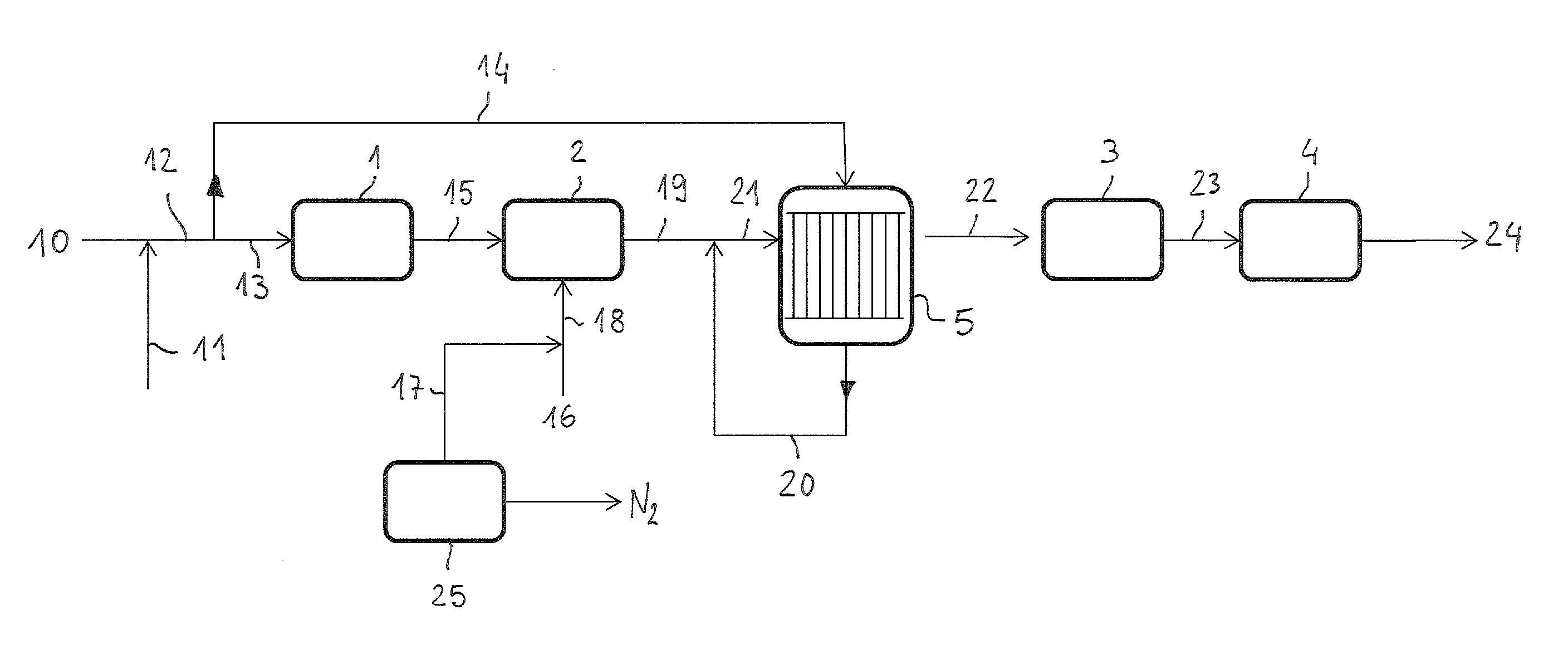
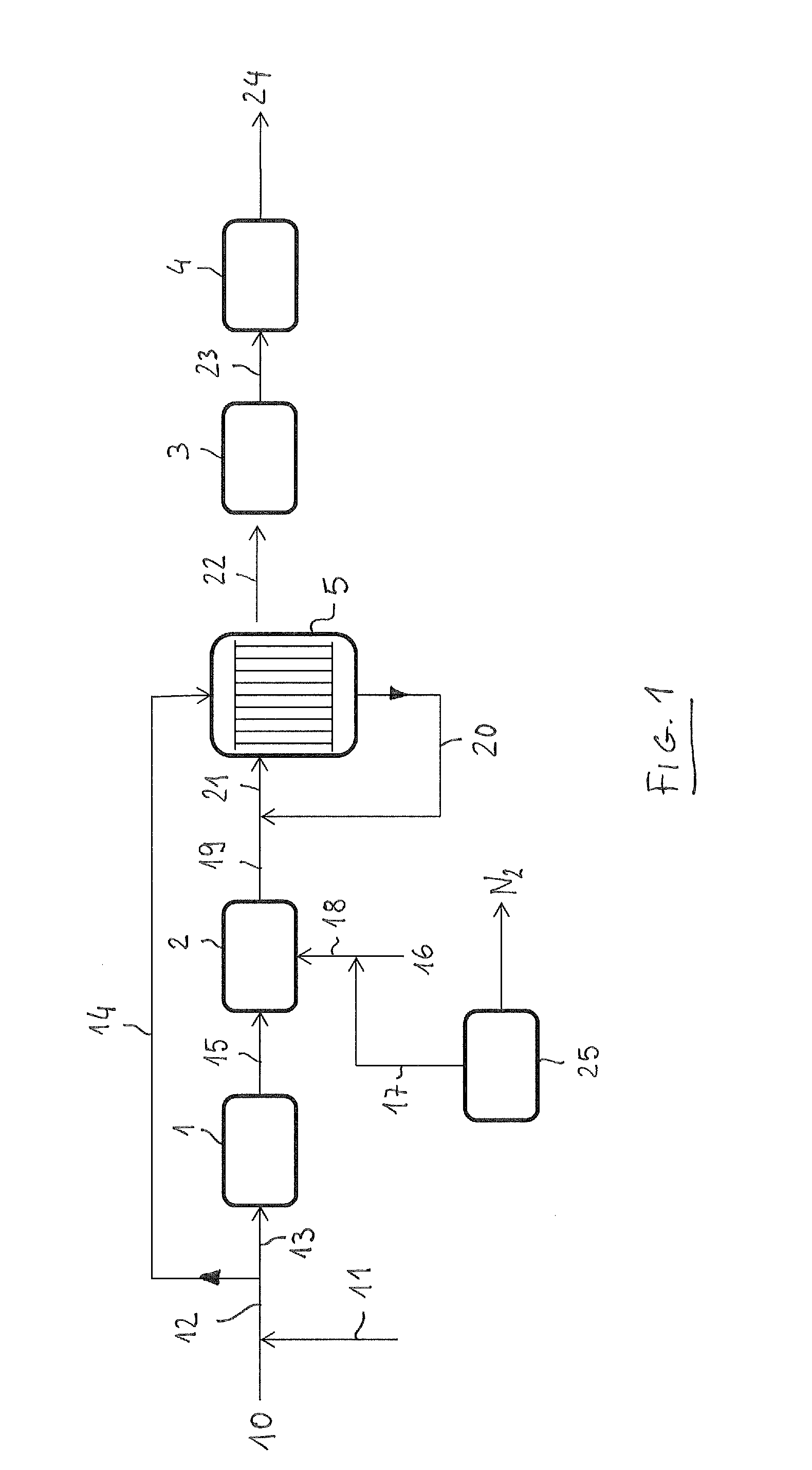
[0030]FIG. 1 illustrates a front-end of an ammonia plant including a tube primary reformer 1, a secondary reformer 2, a shift conversion section 3, a CO2 removal section 4, and a gas-heated reactor (GHR) 5 after the secondary reformer 2, and before the shift conversion section 3.

[0031]Said gas-heated reactor 5 is basically a shell-and-tube equipment for indirect heat exchange between a first current in the tube side and a second current in the shell side. Said first current contains a gaseous hydrocarbon and steam. Said tubes of reactor 5 are filled or coated with a suitable catalyst for steam reforming.

[0032]A gaseous hydrocarbon feedstock, for example desulphurized natural gas 10, is added with steam 11 forming a mixed flow 12. A first part 13 of said mixed flow 12 is directed to the tubes of the primary reformer 1, and the remaining part 14 of said mixed flow 12 is fed to the tube side of the gas-heated reactor 5. Further steam can be added to stream 14, according to some embodim...


PUM

PropertyMeasurementUnit
temperatureaaaaaaaaaa
molar ratioaaaaaaaaaa
temperatureaaaaaaaaaa

Abstract

A process for producing ammonia make-up synthesis gas and a procedure for revamping a front-end of an ammonia plant for producing ammonia make-up synthesis gas are disclosed, wherein the make-up synthesis gas is produced by means of steam reforming of a hydrocarbon gaseous feedstock; said front-end includes a primary reformer, a secondary reformer, a shift conversion section, a CO2 removal section and optionally a methanation section; a shell-and-tube gas-heated reformer is installed after said secondary reformer, and a portion of the available feedstock is reformed in the tubes of said gas-heated reformer, and heat is provided to the shell side of said gas-heated reformer by at least a portion of product gas leaving the secondary reformer, possibly mixed with product gas leaving the tubes of said gas-heated reformer.

Description

FIELD OF THE INVENTION[0001]The invention relates to reforming of hydrocarbons for the preparation of a synthesis gas suitable for the production of ammonia.BACKGROUND ART[0002]Ammonia plants include a front-end for the generation of a synthesis gas, which is then reacted to form ammonia in a synthesis loop. The synthesis gas is generated in the front-end by steam reforming of a hydrocarbon feedstock, for example natural gas or a substitute natural gas (SNG).[0003]A conventional and well known front-end includes: a primary reformer, a secondary reformer, a shift reactor, a CO2 removal section and optionally a methanation section. The purified synthesis gas leaving the CO2 removal section or methanation section has a molar ratio between hydrogen H2 and nitrogen N2 of around 3:1 suitable for the synthesis of ammonia. Said purified gas is then compressed to synthesis pressure and fed to a synthesis loop.[0004]The primary reformer converts methane from the hydrocarbon source and steam i...

Claims


Application Information

Patent Timeline
Patent Type & Authority Applications(United States)
IPC IPC(8): C01B3/02C01B3/48C01B3/50B01J7/00
CPCC01B3/025B01J7/00C01B3/48C01B3/50C01B2203/142C01B2203/0283C01B2203/0475C01B2203/1235C01B2203/0205B01J2219/00024C01B3/382C01B13/0229C01B2203/0233C01B2203/0244C01B2203/043C01B2203/0445C01B2203/068C01B2203/0844C01B2203/141C01B2210/0046C01C1/0405Y10T29/49716Y02P20/52C01B3/26
Inventor FILIPPI, ERMANNOOSTUNI, RAFFAELE
Owner CASALE SA
Why Eureka
Try Eureka