Liquid crystal television and backlight unit

a backlight unit and liquid crystal technology, applied in the field of backlight units, can solve the problems of uneven luminance, increased cost, uneven light emission,

Inactive Publication Date: 2012-02-28
FUNAI ELECTRIC CO LTD
View PDF12 Cites 0 Cited by
  • Summary
  • Abstract
  • Description
  • Claims
  • Application Information

AI Technical Summary

Benefits of technology

[0010]It is an object of the present invention to provide a backlight unit for feeding power to the cold-cathode tubes connected in series from the single inverter circuit transformer, which is capable of suppressing the unevenness of the luminance of the cold-cathode tube, and also to provide a liquid crystal television which employs the backlight unit.
[0012]In the above-structured backlight unit, the series circuit is formed by connecting the inter-lamp coil in series between the cold-cathode tubes. When the tube current applied to one of the cold-cathode tubes is about to rise up, such increase in the tube current may be suppressed by the inter-lamp coil under the electromotive force. This makes it possible to make the difference in the luminance between the cold-cathode tubes uniform, thus preventing the unevenness in the luminance such as the luminance gradient of the backlight.
[0014]In the above-structured backlight unit, the variation in the capacitance of the cold-cathode tube may be absorbed by the capacitance of the capacitors connected in parallel. The pressure difference between two cold-cathode tubes may be reduced to suppress the difference in the tube current. This makes it possible to suppress the luminance difference between the two cold-cathode tubes, thus preventing the unevenness in the luminance such as the luminance gradient.
[0017]According to another aspect of the present invention, a liquid crystal television includes a tuner module for receiving a predetermined channel from a television broadcast signal, a liquid crystal display for displaying an image based on the received television broadcast signal by transmitting light rays, and a backlight unit provided with a first and a second U-shaped cold-cathode tubes for irradiating the light rays onto a backside of the liquid crystal display, a transformer, and a self-excited inverter circuit. The backlight unit connects the first U-shaped cold-cathode tube to one output terminal of a secondary coil of the transformer, and connects the second U-shaped cold-cathode tube to the other output terminal. An inter-lamp coil is connected between the first and the second U-shaped cold-cathode tubes to form a series circuit. A first capacitor and a second capacitor each having an equal capacitance which is at least higher than that of the cold-cathode tube are connected to the first and the second cold-cathode tubes in parallel, respectively. When a high frequency voltage generated by the self-excited inverter circuit is applied to the transformer to illuminate the first and the second cold-cathode tubes, a difference in an applied tube current between the first and the second cold-cathode tubes is reduced.

Problems solved by technology

In the technology disclosed in Japanese Unexamined Patent Application Publication No. 2005-5059, the number of the inverter circuit transformers has to be increased in accordance with the number of the cold-cathode tubes, which results in the cost increase.
In the technology disclosed in Japanese Unexamined Patent Application Publication No. 2005-190835, variation in the tube current fed to the cold-cathode tube may result in uneven luminance.
Even if the constant electromotive force is applied to the secondary coil of the inverter circuit transformer, the variation in the value of the tube current applied through the cold-cathode tube may make the light emitting luminance uneven.
This may result in the uneven luminance of the liquid crystal display, and accordingly, the viewer may feel uncomfortable with the view of the display.

Method used


Image

  • Liquid crystal television and backlight unit
  • Liquid crystal television and backlight unit
  • Liquid crystal television and backlight unit

Examples


Embodiment Construction

[0024]The detailed description set forth below in connection with the appended drawings is intended as description of presently preferred embodiments of the invention and is not intended to represent the only forms in which the present invention may be constructed and or utilized.

[0025]An embodiment and the modified examples according to the present invention will be described with respect to the sections in the following order.

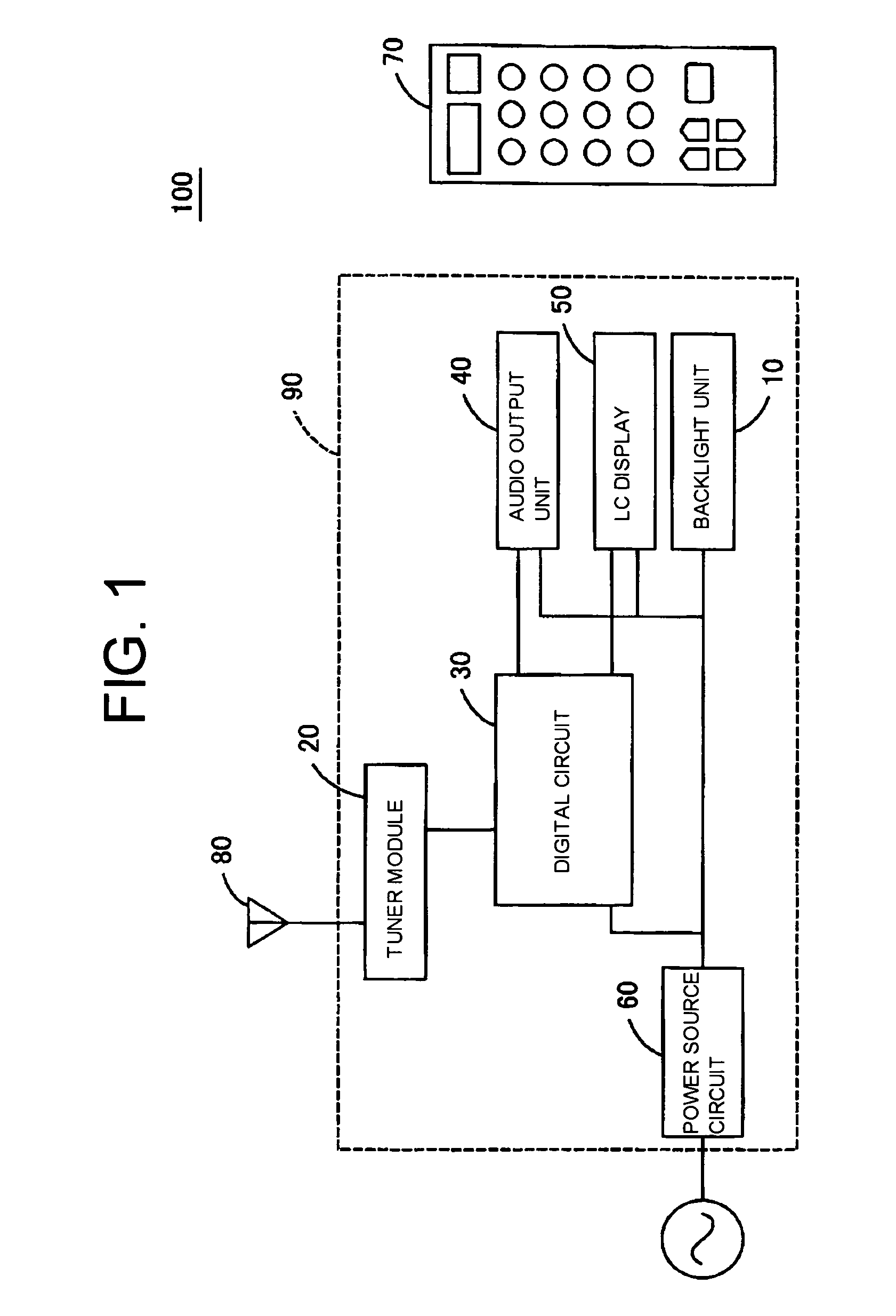
(1) Structure of the liquid crystal television

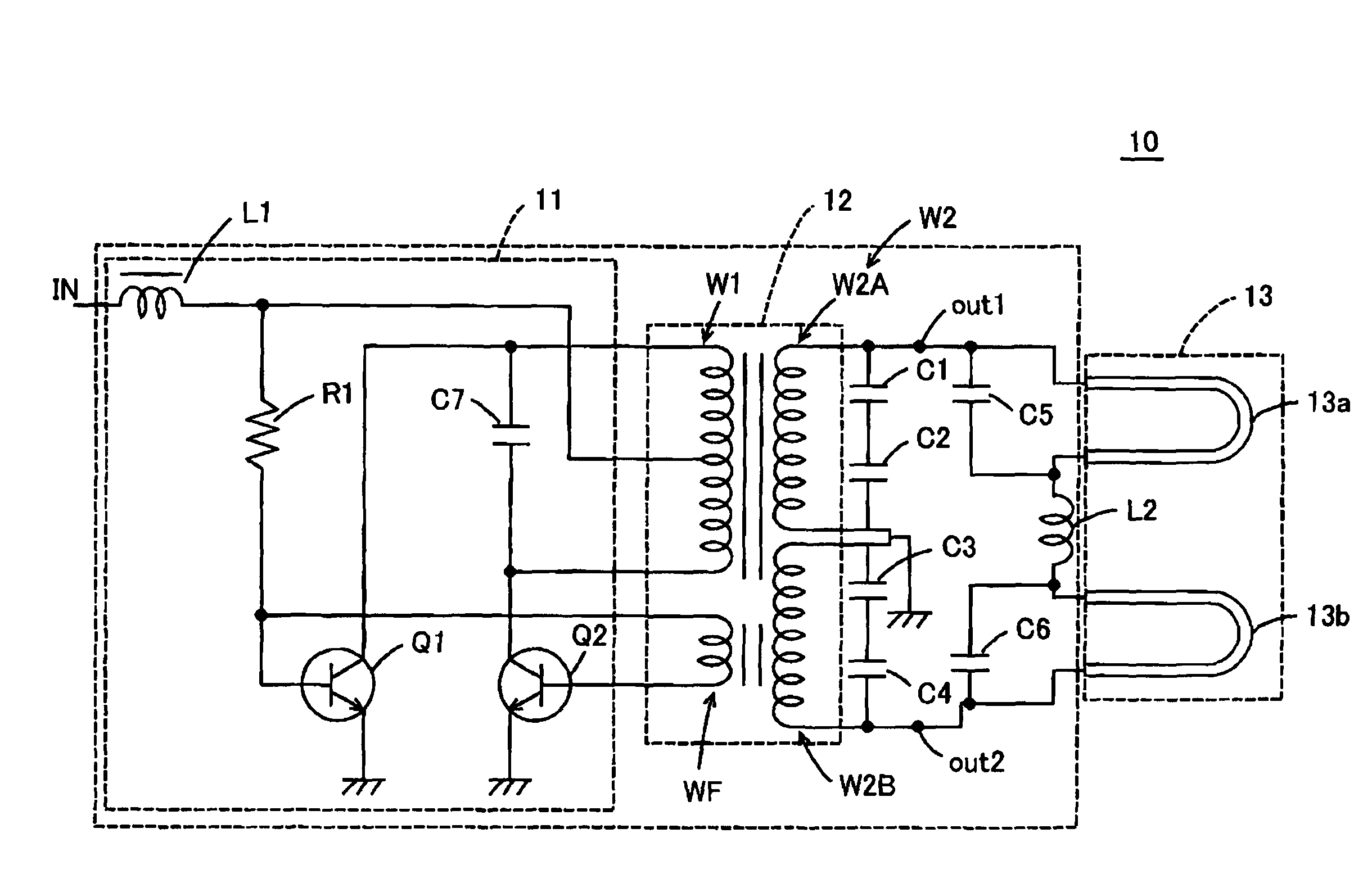
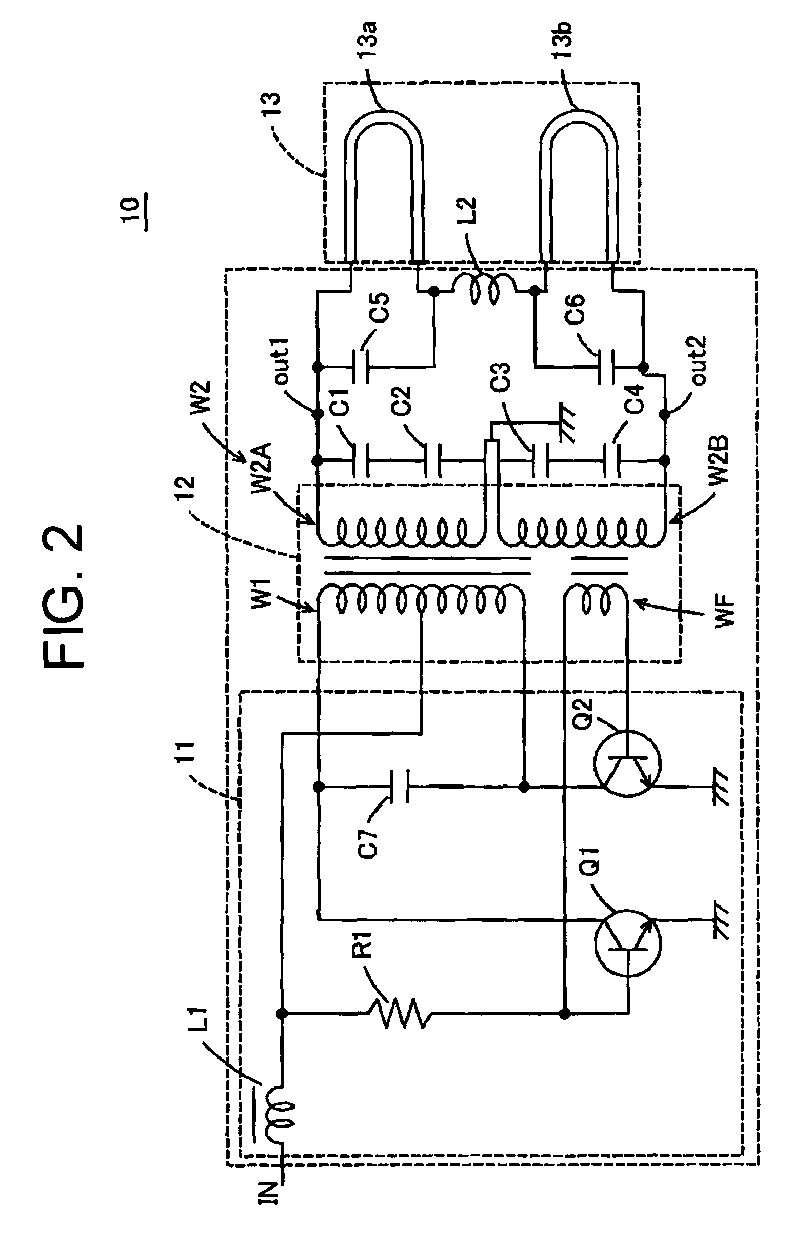
(2) Structure of the backlight unit

(3) Function and effects of the backlight unit

(4) Modified examples

(5) Outline

(1) Structure of the Liquid Crystal Television

[0026]A liquid crystal television displays an image on a liquid crystal display based on the received television broadcast. The liquid crystal display displays the image by transmitting light rays irradiated from the backlight unit onto the back side. The backlight unit generates a light source by driving two U-shaped cold-cathode tubes connected in series a...


PUM


Abstract

A liquid crystal television 100 displays an image on a liquid crystal display by transmitting a light source from a backlight unit 10. The backlight unit 10 drives two cold-cathode tubes 13a, 13b as the backlight 13 at the high frequency voltages each with different polarity generated by a self-excited inverter circuit 11 to generate a light source. The backlight unit 10 connects an inter-lamp coil L2 between two U-shaped cold-cathode tubes 13a, 13b to form a series circuit, and further connects capacitors C5, C6 in parallel with the cold-cathode tubes 13a, 13b.

Description

CROSS-REFERENCES TO RELATED APPLICATIONS[0001]The present application is related to the Japanese Patent Application No. 2007-104987, filed Apr. 12, 2007, the entire disclosure of which is expressly incorporated by reference herein.BACKGROUND OF THE INVENTION[0002]1. Field of the Invention[0003]The present invention relates to a backlight unit which feeds power to a cold-cathode tube, and more particularly to a backlight unit which feeds power to a plurality of cold-cathode tubes connected in series from a single inverter circuit transformer, and further relates to a liquid crystal television which employs the backlight unit.[0004]2. Description of Related Art[0005]Generally, the backlight unit for driving the backlight which illuminates the liquid crystal display from the back side has been well known. The backlight unit feeds AC power generated by the separately-excited or self-excited inverter circuit transformer to the backlight so as to be illuminated.[0006]Japanese Unexamined P...

Claims


Application Information

Patent Timeline
Patent Type & Authority Patents(United States)
IPC IPC(8): H04N3/14G09G3/36
CPCH05B41/2822Y02B20/185Y02B20/00
Inventor MIYAMOTO, HITOSHI
Owner FUNAI ELECTRIC CO LTD
Why Eureka
Try Eureka