Self-propelled vacuum-cleaning device

a vacuum cleaning and self-propelled technology, applied in vacuum cleaners, electrochemical generators, applications, etc., can solve the problems of disadvantage, comparatively heavy power sources, inability to effectively clean textile floor coverings, etc., and achieve good vacuuming results and sufficient traction

Active Publication Date: 2012-03-06
WESSEL WERK
View PDF13 Cites 27 Cited by
  • Summary
  • Abstract
  • Description
  • Claims
  • Application Information

AI Technical Summary

Benefits of technology

[0003]It is therefore an object of the invention to provide a self-propelled vacuum-cleaning device that demonstrates acceptable cleaning capacity both on smooth floor coverings and on textile floor coverings.
[0007]Preferably, a rechargeable battery unit is provided as the power source. A rechargeable battery unit having a capacity of at least 100 Wh, with which the self-propelled vacuum-cleaning device can be operated for about 30 minutes, is suitable. Within the scope of the invention, manual recharging or automatic recharging in a charging station, to which the vacuum-cleaning tool returns automatically, can be provided. It is also possible that a discharged rechargeable battery unit is replaced with a charged rechargeable battery unit, manually or automatically, for example in the charging station, thereby making it possible to extend the period of operation without a long interruption. In an alternative embodiment of the invention, a fuel cell is provided as a power cell. The fuel cell, which is preferably operated with methane, can be quickly refilled and has a high energy density relative to its weight.
[0008]In one embodiment, the roller drive, the maximal electric power of which is at most 40 watts, i.e. ⅓ of the power of the vacuum blower, drives a single cleaning roller disposed in a brush chamber in the housing through which the vacuuming air flows. With this arrangement, crumbs, lint, and dust can be effectively loosened and removed from smooth floor coverings and from the fibers of textile floor coverings. A brush roller or a blade roller with continuous or segmented soft blades can be used as the cleaning roller.
[0009]The travel direction and speed can easily controlled by using two drive motors in the drive mechanism. Each drive motor has a drive wheel assigned to it, and steering of the vacuum-cleaning tool takes place by variably turning the drive motors on and off. Good maneuverability is also guaranteed by such an embodiment.
[0010]To optimize the vacuuming properties, while keeping the energy consumption of the vacuum-cleaning tool as low as possible, a variable power control of the roller drive assigned to the cleaning roller and / or of the vacuum blower and / or of the drive mechanism, as a function of the composition of the floor covering and / or the degree of dirtiness, is provided. By controlling the drive mechanism, a lower travel speed can be provided on textile floor coverings than on smooth floors. By reducing the travel speed, more intensive cleaning of the floor covering is possible. On smooth floor coverings, dirt particles are relatively easy to remove, so sufficient cleaning can usually be achieved even at a higher speed of travel. Additionally or alternatively to varying the travel speed, the speed of rotation of the vacuum blower can also be regulated. In order to loosen dirt from the fibers of a textile floor covering, a great vacuuming air stream and a correspondingly high speed of rotation of the vacuum blower are typically required. On smooth floor coverings, in contrast, dirt particles loosened by the cleaning roller can be reliably picked up even at a lower vacuuming power, i.e., at a lower speed of rotation of the vacuum blower.
[0012]Sufficient traction between the drive mechanism and textile floor covering is then not guaranteed. By adjusting the height of the drive mechanism, the distance between vacuum-cleaning tool and floor covering can be varied, thereby making it possible to achieve good vacuuming results even on different types of textile floor coverings, such as carpeting or long-pile carpets.

Problems solved by technology

In the case of a lower maximal electric power of the self-propelled vacuum-cleaning tool, the components would have to be designed to be weaker, and effective cleaning of textile floor coverings would not be possible independent of how the power were distributed among the individual components.
In the case of an increase of the maximal electric power above the indicated range, power sources would be required that are comparatively heavy and disadvantageous for that reason.

Method used


Image

  • Self-propelled vacuum-cleaning device
  • Self-propelled vacuum-cleaning device

Examples


Embodiment Construction

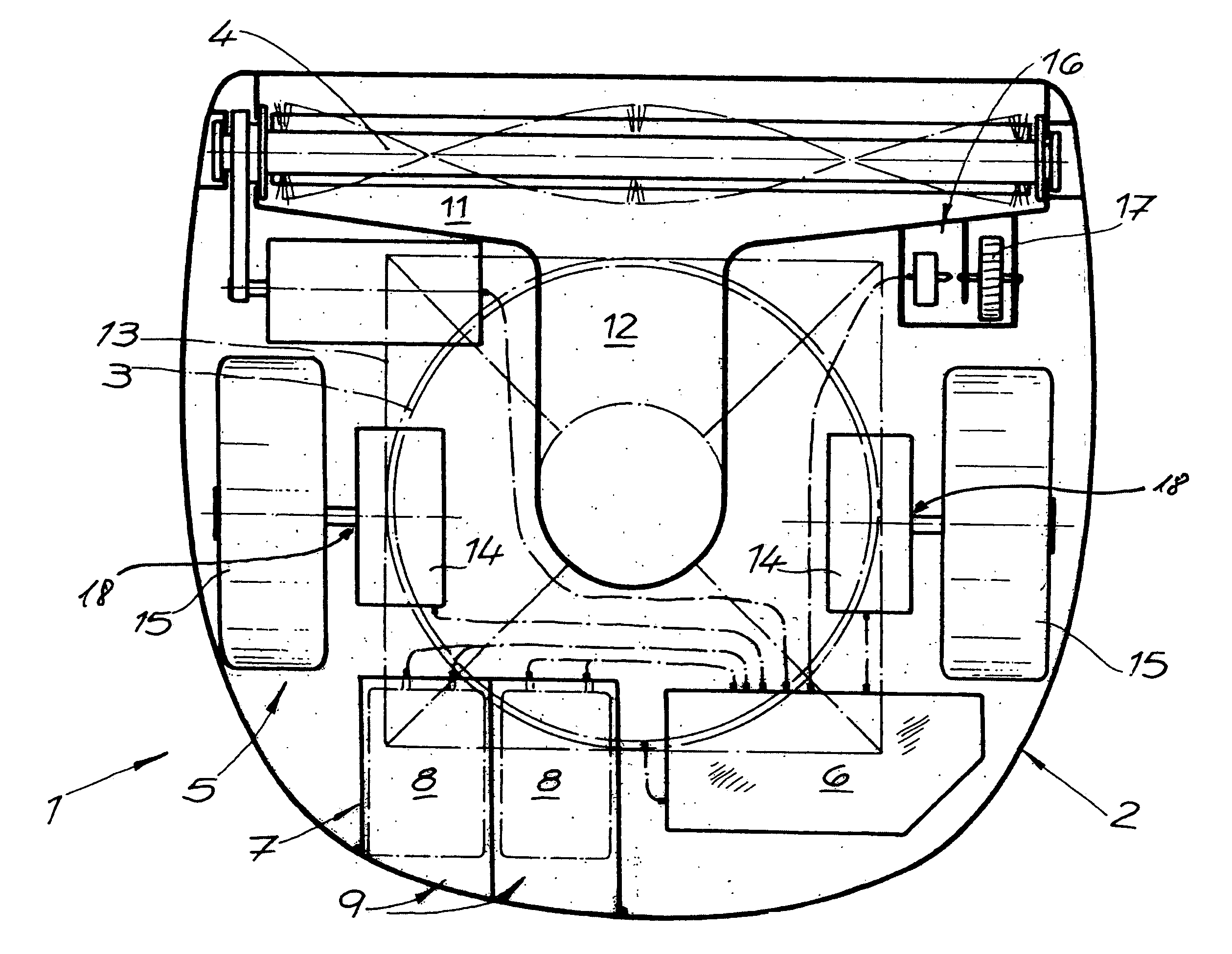
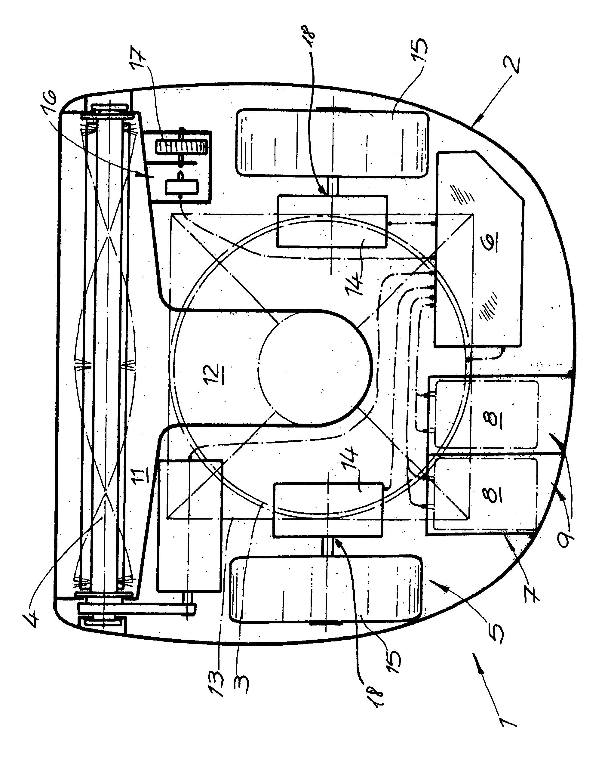
[0015]The single FIGURE shows a self-propelled vacuum-cleaning device for cleaning smooth and textile floor coverings, for example in the private home sector. A vacuum blower 3, an electrically driven cleaning roller 4, an electrical drive mechanism 5, control electronics 6, and a power source 7 are disposed in a housing 2. The maximal electric power of self-propelled vacuum-cleaning device 1 lies at 225 watts, whereby 170 watts are allocated to vacuum blower 3, 25 watts are allocated to the electrical roller drive for cleaning roller 4, 25 watts are allocated to drive mechanism 5, and 5 watts are allocated to control electronics 6, including the sensors, not shown, and displays. A rechargeable battery unit 8 having a capacity of 150 watts is provided as power source 7. Recharging of the rechargeable battery unit takes place in a charging station to which the self-propelled vacuum-cleaning device 1 automatically returns before rechargeable battery unit 8 has been completely discharg...


PUM


Abstract

A self-propelled vacuum-cleaning device for cleaning smooth and textile floor coverings, particularly in the private home sector. The device has a housing, a vacuum blower, an electrically driven cleaning roller, an electrical drive mechanism, control electronics, and a power source. The maximal electric power of the self-propelled vacuum-cleaning tool lies between 150 watts and 300 watts during cleaning operation, whereby between 120 watts and 220 watts are allocated to the vacuum blower, between 10 watts and 40 watts are allocated to the electrical roller drive for the cleaning roller, and between 5 watts and 40 watts are allocated to the drive mechanism, and whereby the control electronics have a power demand of less than 5% of the maximal electric power.

Description

BACKGROUND OF THE INVENTION1. Field of the Invention[0001]The invention relates to a self-propelled vacuum-cleaning device for cleaning smooth and textile floor coverings, particularly in the private home sector. The device has a housing, a vacuum blower, an electrically driven cleaning roller, an electrical drive mechanism, control electronics, and a power source.2. The Prior Art[0002]Self-propelled vacuum-cleaning devices are described in U.S. Pat. No. 5,787,545 and European Patent No. EP 0 803 224 B1, and in various embodiments from practice. The known embodiments have a rechargeable battery as a power source, which is manually or automatically charged in a charging station during breaks in operation. During cleaning, the self-propelled vacuum-cleaning devices are controlled by the control electronics, which act on the electrical drive mechanism. Various contact sensors or sensors that work without contact can be provided to recognize barriers and walls. It is also known to store...

Claims


Application Information

Patent Timeline
Patent Type & Authority Patents(United States)
IPC IPC(8): E01H1/08A47L5/00
CPCA47L9/009A47L9/2826A47L9/2842A47L9/2847A47L9/2852A47L2201/00H01M8/00H01M8/1011H01M10/00Y02B40/82A47L2201/022Y02B40/00Y02E60/50
Inventor DILGER, HORSTKAFFENBERGER, DIETERRIEHL, KLAUS-DIETER
Owner WESSEL WERK
Why Eureka
Try Eureka