Colored mask combined with selective area deposition

a selective area deposition and masking technology, applied in the field of colored masking technique, can solve the problems of affecting the performance and ability to perform alignment of transistor components, affecting the overlay accuracy achievable using traditional photolithography equipment, and applying multiple layers at extremely high speeds, so as to reduce the number of cleaning steps

Inactive Publication Date: 2012-03-06
EASTMAN KODAK CO
View PDF15 Cites 5 Cited by
  • Summary
  • Abstract
  • Description
  • Claims
  • Application Information

AI Technical Summary

Benefits of technology

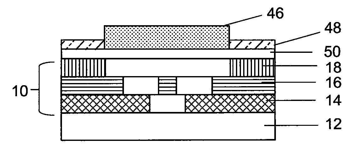
[0023]One advantage of the present invention is that it provides a method for forming aligned layers without the need for expensive alignment equipment and processes. A further advantage of the present invention is that it provides a method for additive patterning of inorganic thin films in a selective area deposition process. There are many potential advantages to selective area deposition techniques, such as eliminating an etch process for film patterning, reducing the number of cleaning steps required, patterning materials that are difficult to etch, and patterning layered structures that are difficult to etch selectively. Another advantage is that a multicolor mask can be used to enable automatic alignment of layers, which multicolor mask can be prepared directly on the support in color-encoded form ensuring that the correct mask is used. Additionally, deposition inhibitor materials that are patterned using a visible light exposure as proposed can be used to pattern all layers of a transistor structure directly on a color mask, for example a transistor comprising a transparent oxide semiconductor such as materials based on zinc oxide. The multicolor mask has the advantage of containing more independently addressable levels than a grayscale mask and works particularly well for patterning transparent electronic materials.

Problems solved by technology

At the other extreme, conventional printing techniques such as offset lithography, flexography, and gravure printing also apply multiple layers at extremely high speeds, although at substantially lower overlay accuracy.
In spite of the potential advantages of flexible substrates, there are many issues affecting the performance and ability to perform alignments of transistor components across typical substrate widths up to one meter or more.
In particular, for example, the overlay accuracy achievable using traditional photolithography equipment can be seriously impacted by substitution of a flexible plastic substrate for the rigid glass substrates traditionally employed.
Three types of registration errors are common in these fabrication processes: fixed errors, scale errors, and local misalignments.
In addition to fixed errors, scale errors may also be substantial.
Errors in pattern scale are cumulative across the substrate and arise from support dimensional change, thermal expansion, and angular placement errors of the substrate with the patterning device.
Although the motion control system impacts angular placement, pattern scale mismatch is largely driven by the characteristics of the support.
Thermal expansion, expansion from humidity or solvent exposure, shrinkage from high temperature exposure, and stress relaxation (creep) during storage of the support all contribute to pattern scale errors.
Further, local pattern mismatch arising from nonisotropic deformations may also occur, particularly since the conveyance process involves applying tension.
Unfortunately, these technologies ultimately produce a flexible electronics component only with the cost structure of current glass based processing.
It is difficult to imagine significant equipment cost difference or throughput advantage, particularly if the added task of distortion compensation is included.
Most of these methods allow self alignment of one layer to another layer, but do not significantly remove the need for very sophisticated alignment steps between several layers.
There are difficulties with the SAIL process, however.
Second, the SAIL process requires high accuracy etch depth control, which may not be consistent with a low cost process.
Finally, a significant limitation of the SAIL process is that layers produced by the mask cannot be fully independent.
As an example, it is particularly challenging to form openings under continuous layers with this approach, an essential element in a matrix backplane design.
These deposition and subtractive patterning methods have high capital costs and preclude the easy use of continuous web-based systems.
The problem with these previously used director inhibitors is that they are only effective to direct selected thin materials.
Additive methods of patterning director inhibitors, such as lithography or inkjet are limited in their resolution.
Also, there remains a difficulty in aligning the different layers in a final device that cannot be resolved by selected area deposition alone.

Method used


Image

  • Colored mask combined with selective area deposition
  • Colored mask combined with selective area deposition
  • Colored mask combined with selective area deposition

Examples


example 1

Multicolor Mask Formed by Direct Printing Process

[0180]In this example, a multicolor mask was prepared containing three color absorbing layers, with each color corresponding to an individual functional layer of an array of thin film transistor devices. The design for the gate layer of the array of thin film transistor devices was converted into a black and white bitmap file. The design for the semiconductor layer of the array of thin film transistor devices was converted into another black and white bitmap file. The design for the source and drain layer of the array of thin film transistor device was converted into a third black and white bitmap file. These bitmaps were then imported into the blue channel, green channel, and red channel of a single color image file using Photoshop 6.0. In this full color image, the blue channel contained the gate layer design as a yellow pattern. The green channel contained the semiconductor layer design as a magenta pattern. The red channel contain...

example 2

Multicolor Mask Formed by Photolithography Process

[0181]In this example, a multicolor mask was prepared containing three color absorbing layers, with each color corresponding to an individual functional layer of an array of thin film transistor devices. Chrome on glass masks for the gate layer (CG-1), semiconductor and dielectric layers (CG-2), and source and drain layers (CG-3) of the array of thin film transistor devices were obtained from Applied Image Incorporated. A 0.7 mm thick borosilicate glass support was washed for 10 minutes by treating with a solution of 70% sulfuric acid and 30% of a 30% solution of hydrogen peroxide maintained at approximately 100° C. After washing, the clean glass was spin coated (at 1000 RPM) with Color Mosaic SC3200L (purchased from Fujifilm Electronic Materials Co., Ltd.). SC-3200L is a UV curable photoresist containing 3-5% of a cyan pigment, 7-9% of a methacrylate derivative copolymer, 7-9% of a polyfunctional acrylate resin and a UV photosensiti...

example 3

Blue-Curable Film Formulation

[0184]A coating solution C-1 for the blue light curable film was prepared as follows. A solution of blue sensitive photoinitiator was prepared by adding 0.03 g of photoinitiator A to 3 grams of toluene.

Photoinitiator A:

[0185]

[0186]In a separate vial, five grams of polymethylmethacrylate (PMMA) (MW ˜75K) were dissolved in 45 g of anisole. To 2.9 g of the resulting PMMA solution, 0.95 g of trimethylolpropane triacrylate and 0.5 g of the solution of photoinitiator A were added.

Green-Curable Film Formulation:

[0187]A coating solution C-2 for the green light curable film was prepared as follows. A solution of green sensitive photoinitiator was prepared by adding 0.03 g of photoinitiator B to 3 grams of anisole. In a separate vial, five grams of PMMA (MW ˜75K) were dissolved in 45 g of anisole. To 2.9 g of the resulting PMMA solution, 0.95 g of trimethylolpropane triacrylate and 0.5 g of the solution of photoinitiator B were added.

Photoinitiator B:

[0188]


PUM

PropertyMeasurementUnit
temperatureaaaaaaaaaa
absorption wavelengthaaaaaaaaaa
optical densityaaaaaaaaaa

Abstract

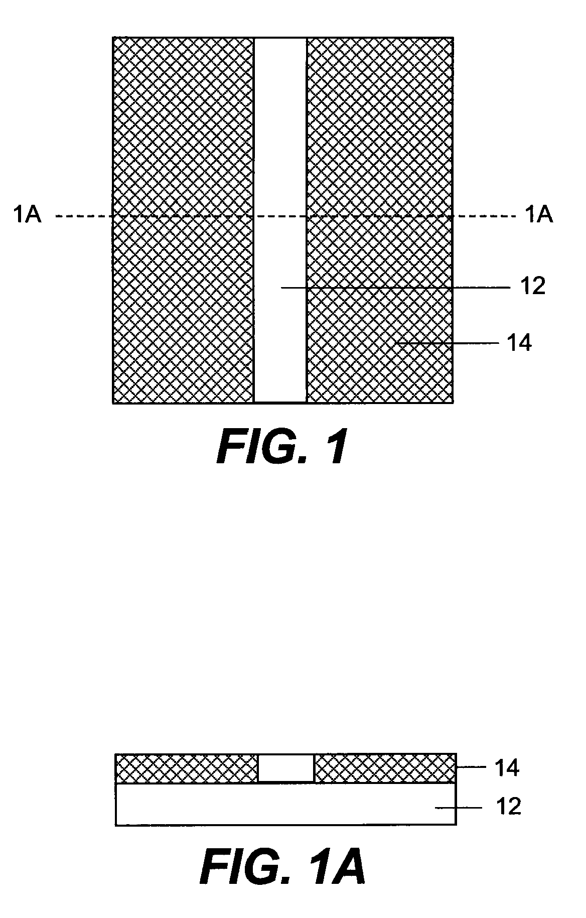
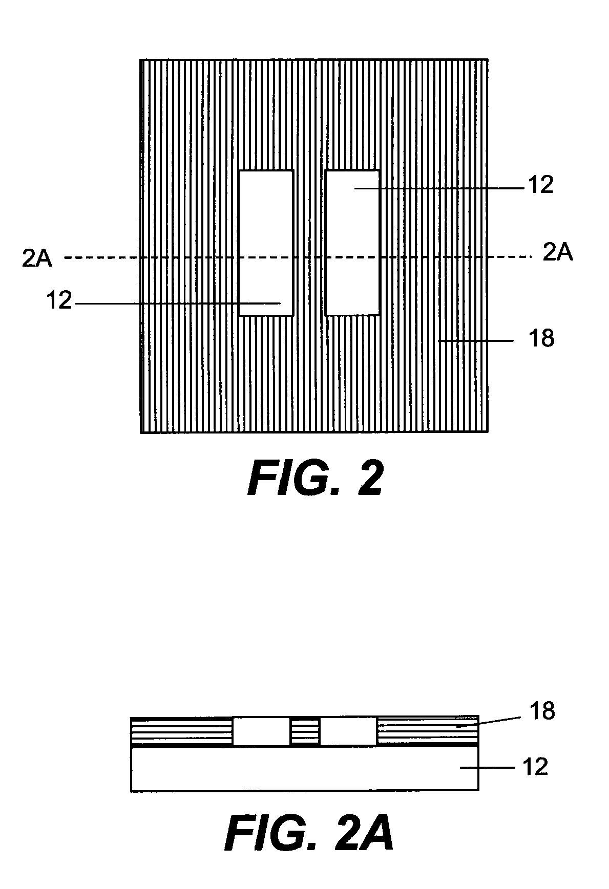
The invention relates to a process for forming a structure comprising (a) providing a transparent support; (b) forming a color mask on a first side of the transparent support; (c) applying a first layer comprising a deposition inhibitor material that is sensitive to visible light; (d) patterning the first layer by exposing the first layer through the color mask with visible light to form a first pattern and developing the deposition inhibitor material to provide selected areas of the first layer effectively not having the deposition inhibitor material; and (e) depositing a second layer of functional material over the transparent support; wherein the second layer of functional material is substantially deposited only in selected areas over the transparent support not having the deposition inhibitor material.

Description

CROSS-REFERENCE TO RELATED APPLICATIONS[0001]Reference is made to commonly assigned U.S. application Ser. No. 11 / 986,155, filed concurrently by Irving et al. and entitled, “COLORED MASK FOR FORMING TRANSPARENT STRUCTUES,” U.S. application Ser. No. 11 / 942,780, filed concurrently by Irving et al. and entitled “PHOTOPATTERNABLE DEPOSTION INHIBITOR CONTAINING SILOXANE,” U.S. application Ser. No. 11 / 986,102, filed concurrently by Irving et al. and entitled “MULTICOLOR MASK,” U.S. application Ser. No. 11 / 986,068, filed concurrently by Irving et al. and entitled “INTEGRATED COLOR MASK,” U.S. application Ser. No. 11 / 986,189, filed concurrently by Irving et al. and entitled, “GRADIENT COLORED MASK,” and U.S. application Ser. No. 11 / 986,088, filed concurrently by Irving et al. and entitled, “MULTICOLORED MASK PROCESS FOR MAKING DISPLAY CIRCUITRY.” All the above-identified applications incorporated by reference in their entirety.FIELD OF THE INVENTION[0002]The invention relates to a colored ma...

Claims


Application Information

Patent Timeline
Patent Type & Authority Patents(United States)
IPC IPC(8): G03F7/20
CPCG03F7/0005G03F7/2022H01L27/1214H01L27/1225H01L29/66765H01L29/7869H01L27/1288H01L27/1292
Inventor IRVING, LYN M.FREEMAN, DIANE C.COWDERY-CORVAN, PETER J.YANG, CHENGLEVY, DAVID H.
Owner EASTMAN KODAK CO
Why Eureka
Try Eureka