Image capture device capable of improved image capturing in electronic viewfinder mode

a technology of electronic viewfinder and image capture device, which is applied in the field of single lens reflex image capture device with electronic viewfinder mode, can solve the problems of inability to carry out light adjustment in flash photography, light cannot be measured with dedicated light measurement sensor, and the through image and the actual image are slightly different, so as to achieve good image capture and improve the ease of use for users

Inactive Publication Date: 2012-03-06
FUJIFILM CORP
View PDF9 Cites 1 Cited by
  • Summary
  • Abstract
  • Description
  • Claims
  • Application Information

AI Technical Summary

Benefits of technology

[0020]According to the present invention, when an electronic viewfinder mode is set and a through image is displayed on a display unit, adjustment is made according to the image capture conditions during through image display of at least one of the through image display conditions during through image display and / or of the main image capture conditions during main image capture. This thereby enables good image capture of a photographic subject in the electronic viewfinder mode.
[0028]Configuration may be made to further include a focusing mode switching unit that switches between an auto focus mode in which focusing operation of the photographic subject is carried out automatically and a manual focus mode in which focusing operation of the photographic subject is carried out manually, such that when the electronic viewfinder mode is set the control unit override-switches to the manual focus mode. Thereby, even when the electronic viewfinder mode is set and the auto focus mode is set there is no need to manually switch over to the manual focus mode in order to make a fine adjustment to the focus, enabling an improvement in the ease of use for a user.

Problems solved by technology

A problem arises, however, that in the electronic viewfinder mode there are slight differences between the through image and the actual image during image capture.
However, in the electronic viewfinder mode there is the problem that light cannot be measured with the dedicated light measurement sensor, and that light adjustment cannot be carried out in flash photography.
In such conventional single lens reflex digital cameras there is the problem that good image capture is difficult in the electronic viewfinder mode.

Method used


Image

  • Image capture device capable of improved image capturing in electronic viewfinder mode
  • Image capture device capable of improved image capturing in electronic viewfinder mode
  • Image capture device capable of improved image capturing in electronic viewfinder mode

Examples


first exemplary embodiment

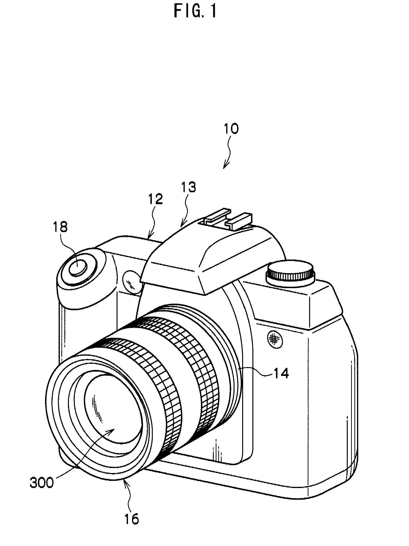
[0051]Explanation will now be given of a digital camera according to the first exemplary embodiment of the present invention. As shown in FIG. 1, a digital camera 10 is a steel single lens reflex digital camera.

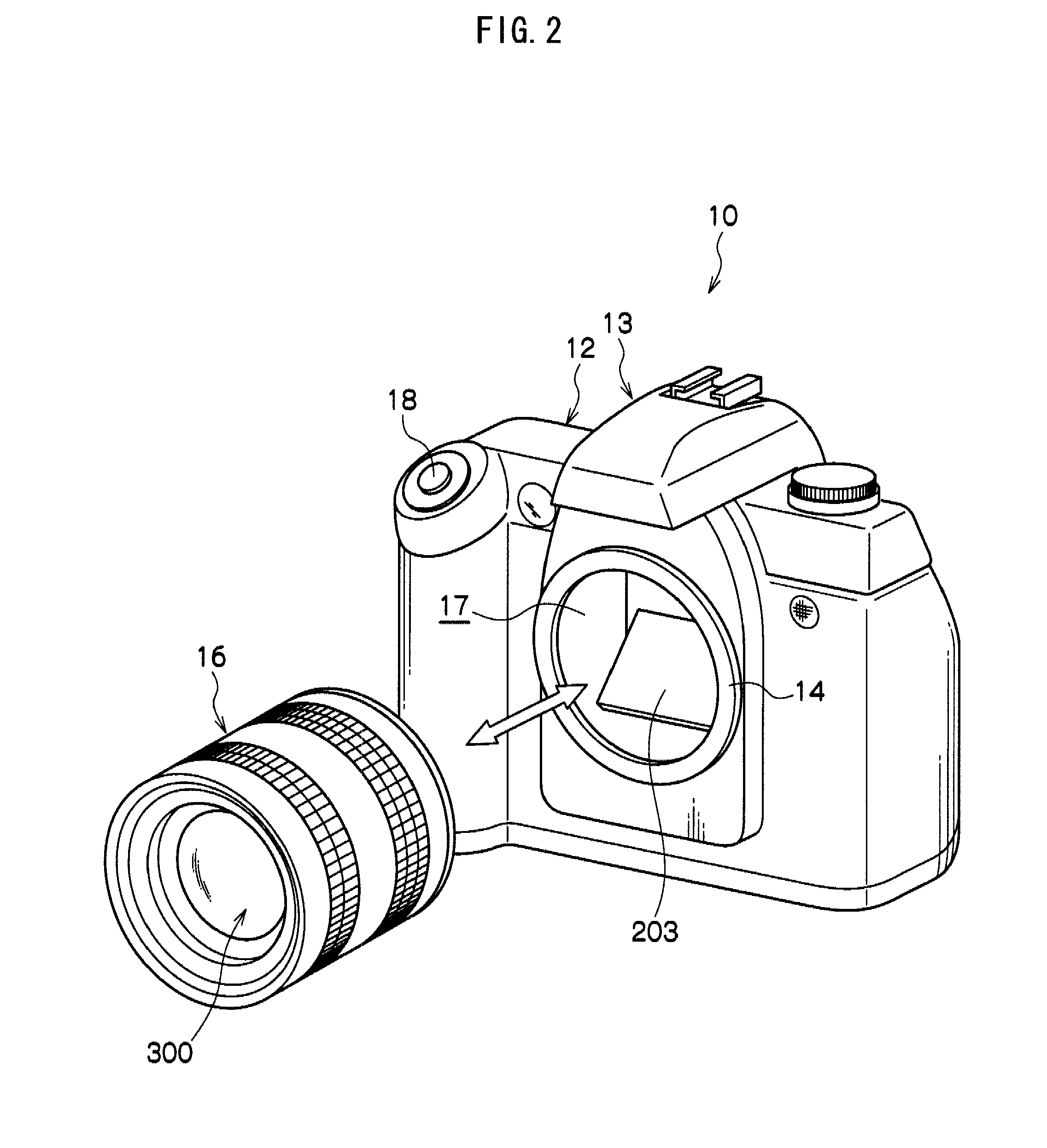
[0052]The digital camera 10, as shown in FIGS. 1 and 2, includes a lens mount portion 14 provided to a front face portion of a camera body 12. A lens unit 16, provided with a lens set 300 (see FIG. 4) made up from plural lenses, is exchangeably mounted via the lens mount portion 14. There is also a shutter button 18 disposed when facing the front face at a top left portion thereof. There is also a flash 13 for emitting auxiliary light provided at a central portion when facing the front face. The flash 13 is configured so as to automatically pop up and emit a flash during image capturing when image capture by flash emission is set. In FIGS. 1 and 2 the flash 13 is shown in the closed state. Setting flash emission may also be undertaken by manually popping up the flash 13 so th...

second exemplary embodiment

[0118]Explanation will next be given of a second exemplary embodiment of present invention. In the second exemplary embodiment, explanation will be made regarding when the settings of the sensitivity and exposure are changed by user operation in the electric viewfinder mode. Those portions that are similar to those of the first exemplary embodiment are allocated the same reference numerals and detailed explanation thereof is omitted.

[0119]A flow chart of image capture processing according to the second exemplary embodiment is shown in FIG. 11. The points therein that differ from those of the flow chart shown in FIG. 6 are only that the steps 403A, 403B have been added, and since other points are the same as those in FIG. 6, explanation thereof is omitted.

[0120]When the electronic viewfinder start processing is executed in step 402 of FIG. 11, the routine proceeds to step 403A.

[0121]In step 403A, determination is made as to whether or not the settings of the main image capture condit...

third exemplary embodiment

[0124]Explanation will now be given of a third exemplary embodiment of the present invention. Explanation will be given relating to when light adjustment of the flash is appropriately performed in the third exemplary embodiment for main image capture with flash emission. Portions that are similar to the above exemplary embodiments are allocated the same reference numerals and detailed explanation thereof is omitted.

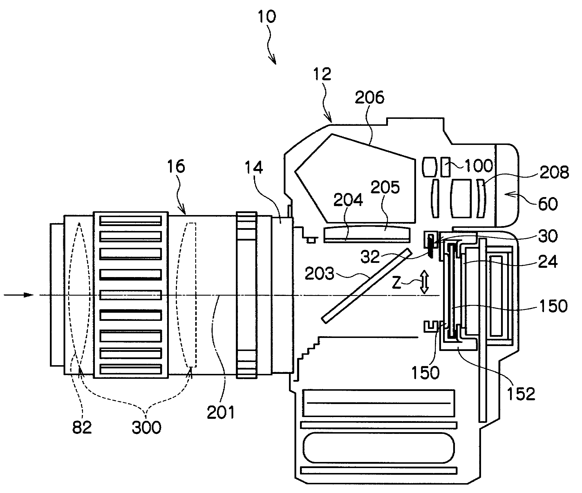
[0125]It is normal in flash image capture with an ordinary single lens reflex digital camera, as described above, for a pre-emission to be carried out, the light measured, followed by the main emission and image capture. However, as shown in FIG. 4, when in the electronic viewfinder mode light measurements cannot be made with the AE sensor 100 since the AE sensor 100 is provided on the optical viewfinder 60 side. Consequently in the present exemplary embodiment, luminance correction gain is computed based on image data from an image captured without flash emission and bas...


PUM


Abstract

The object is to provide an image capture device capable of carrying out good image capture in electronic viewfinder mode. When the electronic viewfinder mode is set in a single lens reflex digital camera a quick return mirror is driven so as to direct light from a photographic subject onto a CCD, and control is also carried out such that images captured by the CCD are displayed as a through image on a liquid crystal monitor at specific time intervals, with the through image display conditions being adjusted so that the image displayed as a through image is an image equivalent to an image that would be captured during main image capture with the set main image capture conditions.

Description

CROSS-REFERENCE TO RELATED APPLICATION[0001]This application claims priority under 35 USC 119 from Japanese Patent Application No. 2007-283507 filed on Oct. 31, 2007.BACKGROUND[0002]1. Technical Field[0003]The present invention relates to an image capture device, and in particular to a single lens reflex image capture device with an electronic viewfinder mode.[0004]2. Related Art[0005]Single lens reflex digital cameras with exchangeable lenses are generally conventionally configured so as to be able to selectively direct light from a photographic subject to one or other of an optical viewfinder or an image capture element such as a CCD, by use of a quick return mirror, such that light is only guided from the photographic subject to the image capture element when an image is being captured.[0006]There are among such single lens reflex digital cameras those capable of switching between an optical viewfinder mode for confirming the photographic subject with the optical viewfinder, and ...

Claims


Application Information

Patent Timeline
Patent Type & Authority Patents(United States)
IPC IPC(8): H04N5/222H04N5/225H04N5/232
CPCH04N5/23293H04N23/65H04N23/632
Inventor MATSUI, SEIICHI
Owner FUJIFILM CORP
Why Eureka
Try Eureka