Laser ranging, tracking and designation using 3-D focal planes

a focal plane and laser technology, applied in the direction of reradiation, distance measurement, instruments, etc., can solve problems such as pixel blurring, and achieve the effects of low energy requirements for operation, low weight, and mechanical simplicity

Active Publication Date: 2012-03-06
CONTINENTAL AUTONOMOUS MOBILITY US LLC
View PDF8 Cites 45 Cited by
  • Summary
  • Abstract
  • Description
  • Claims
  • Application Information

AI Technical Summary

Benefits of technology

[0012]Among the advantages of this device is the novel use of technology having mechanical simplicity and low energy requirements for operation. The low weight and low volume for the device are additional advantages and stem from the mechanical simplicity, the low energy requirements or both. Other advantages and uses of the invention will be apparent to those skilled in the art.

Problems solved by technology

During the time it takes light to reach the target and return to the sensor, mechanical systems typically do not move fast enough to cause pixel blurring.

Method used


Image

  • Laser ranging, tracking and designation using 3-D focal planes
  • Laser ranging, tracking and designation using 3-D focal planes
  • Laser ranging, tracking and designation using 3-D focal planes

Examples


Embodiment Construction

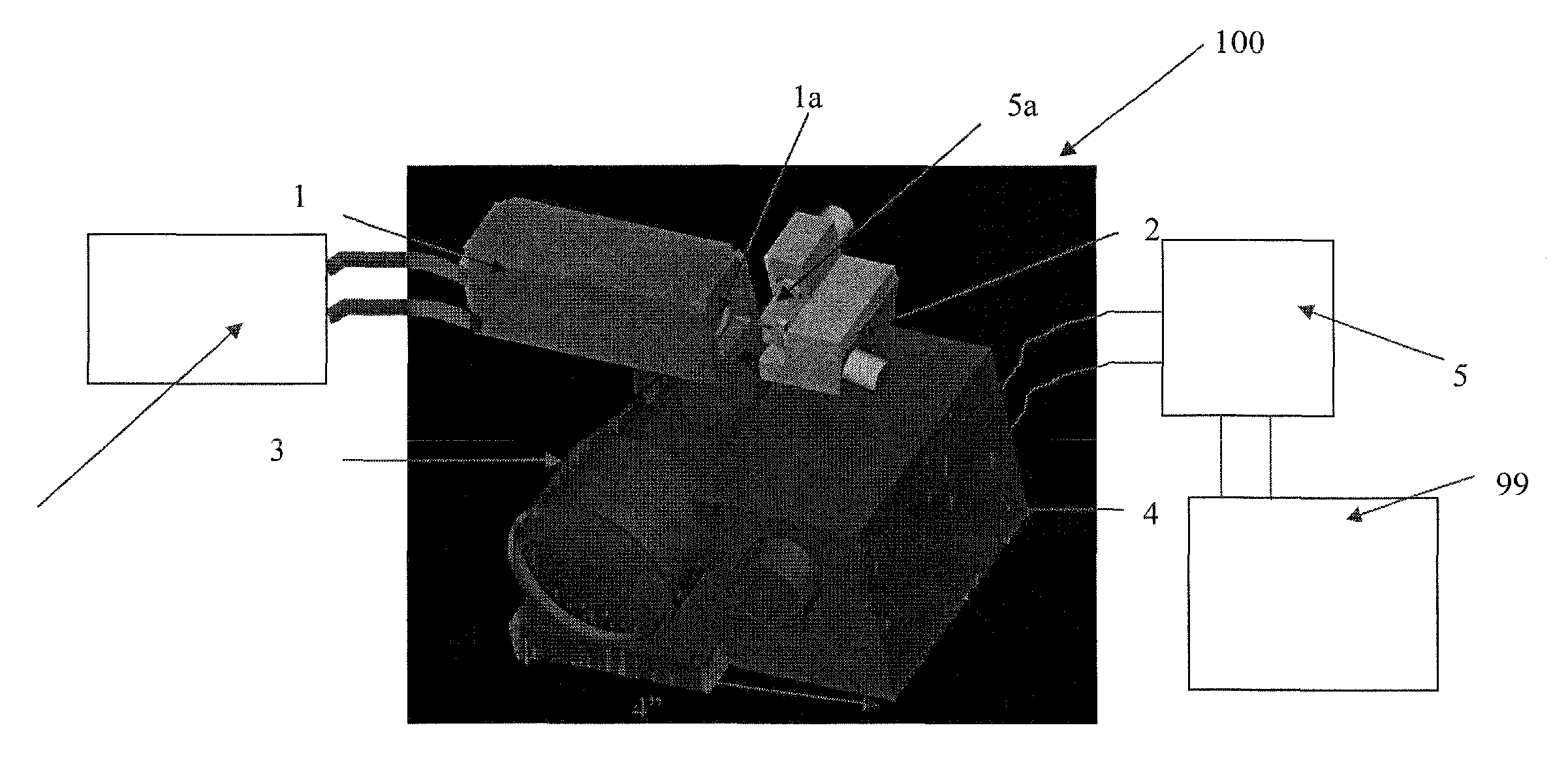
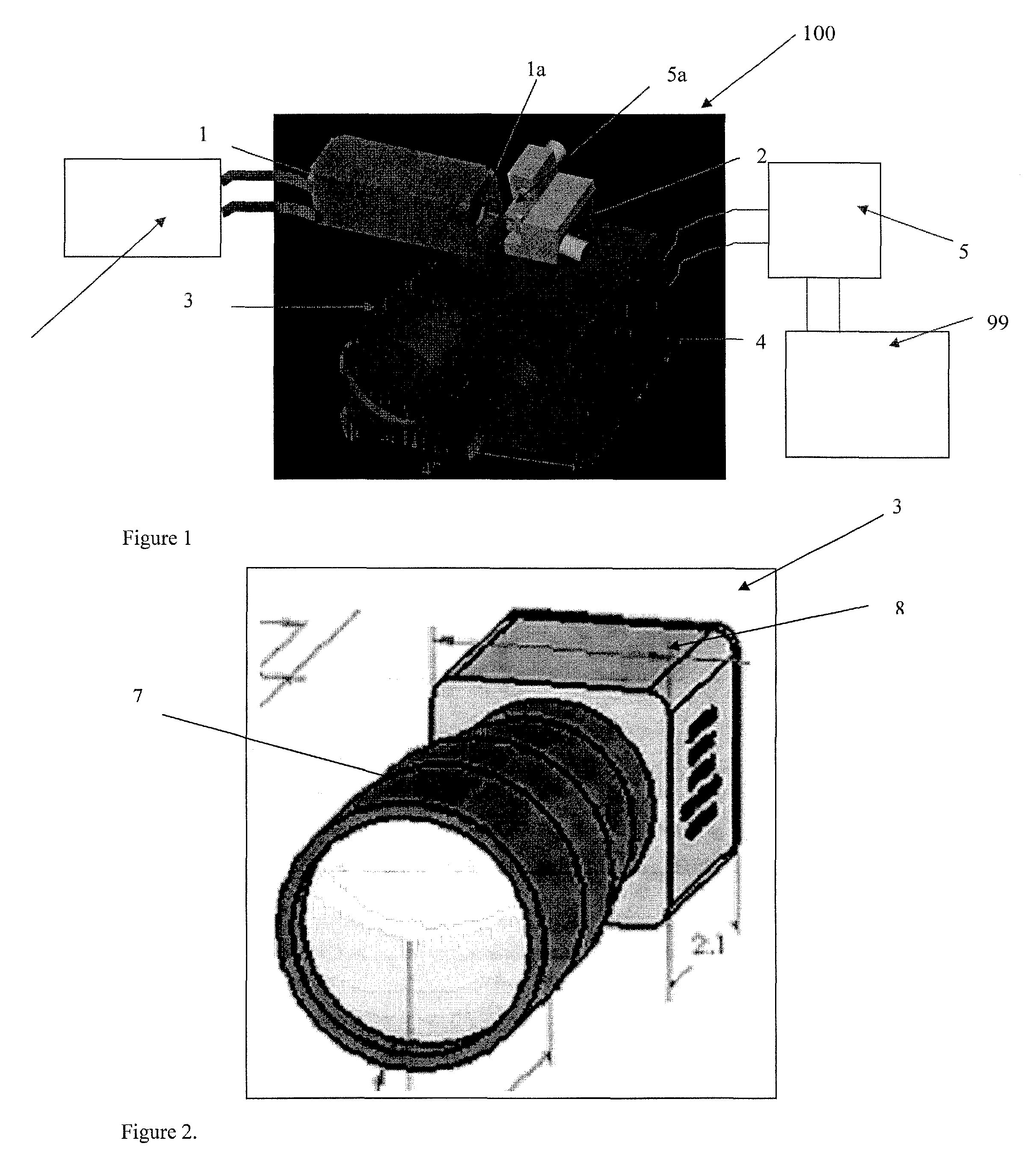
[0020]When generating a flash image with a 3-D FPA each pixel must receive enough laser energy so that a 3-D image can be generated. The farther the object of interest is from the camera the greater the output laser energy required. Since for long-range systems, cost and power is related to the laser energy, reducing the requirement for laser power is a benefit. If the object of interest is only a few pixels in size, is far away, and could be anywhere in the entire field of view of the 3-D FPA, it is most economical to narrow the transmitted laser beam to be only a few pixels in width and to scan the laser beam. Since scanning a laser beam requires only a very small, inexpensive and extremely reliable galvanometer scanner the present invention replaces the full flash ladar system by a cheaper, lower power and sometimes-lower weight and lower volume Energy-Reduced Flash Ladar System (ERFLS).

[0021]In one embodiment a 2-D sensor acquires the object of interest and passes the 2-D coordi...


PUM


Abstract

By using 3-D focal plane arrays, the present invention tracks or locates small moving objects, or generates a 3-D frame of data with minimum laser energy and a minimum of mechanically moving parts. In another embodiment the invention is used to determine the direction of a laser designating a target with a minimum of moving parts. In another embodiment the invention is used as a 3-D movie / video camera. In yet another embodiment the device is used to provide data for autonomous navigation.

Description

[0001]This application claims priority of U.S. Provisional Application 60 / 748,690, filed Dec. 8, 2005.FIELD OF THE INVENTION[0002]This invention relates to laser pulse imaging of three dimensional objects. In particular it relates to embodiments of such technology for target acquisition and tracking, collision avoidance or navigation.BACKGROUND OF THE INVENTION[0003]The 3-D imaging technology disclosed in Stettner et al, U.S. Pat. Nos. 5,446,529, 6,133,989 and 6,414,746 provides the use of a single pulse of laser light to capture the information and content of a 2-D image along with a third dimension depth coordinate; thereby providing the 3-D coordinates of object points in its field of view. This has been referred to as flash 3-D imaging in analogy with ordinary digital 2-D cameras using flash attachments for a self contained source of light. As with ordinary 2-D digital cameras, the light reflected from an object is focused by a lens onto the focal plane of the camera, which is d...

Claims


Application Information

Patent Timeline
Patent Type & Authority Patents(United States)
IPC IPC(8): G01C3/08G01S17/93G01S7/4863G01S17/87G01S17/894G01S17/931
CPCG01S7/4813G01S7/4814G01S7/4863G01S17/66H04N13/0253G01S17/89G01S17/936G06T7/2093G01S17/87G06T7/292H04N13/254G01S17/894G01S17/93G01C21/20G01S17/931G05D1/02
Inventor STETTNER, ROGERBAILEY, HOWARD W.
Owner CONTINENTAL AUTONOMOUS MOBILITY US LLC
Why Eureka
Try Eureka