Rolling container assembly with mount structure

a technology of rolling container and mounting structure, which is applied in the direction of revolving cabinets, transportation items, furniture parts, etc., can solve the problems that the tool container assembly also does not have removable storage containers

Active Publication Date: 2012-03-13
THE STANLEY WORKS ISRAEL
View PDF41 Cites 80 Cited by
  • Summary
  • Abstract
  • Description
  • Claims
  • Application Information

AI Technical Summary

Benefits of technology

[0005]Another aspect of the present invention provides an apparatus for transporting articles between working locations. The apparatus includes one or more rotatable ground engaging wheels mounted towards the bottom of the apparatus for rotation about an axis to provide rolling support for the apparatus. The apparatus also includes a lower drawer having an interior space in which articles to be transported can be stored and an upper drawer disposed above the lower drawer. The apparatus further includes a slide structure having a first portion mounted to the upper drawer and a second portion mounted to the lower drawer to facilitate movement of the upper and lower drawers between open and closed positions, wherein in the closed position, an upwardly facing opening of the lower drawer is disposed beneath the upper drawer. The lower drawer and upper drawer are independently movable between their respective open and closed positions. The apparatus also includes a manually engageable pulling handle. The pulling handle and the one or more ground engaging wheels are arranged to enable a user to manually pull the pulling handle generally rearwardly so as to tilt the apparatus rearwardly to a tilted rolling movement position, thereby enabling the user to roll the apparatus to a desired location by pushing or pulling the pulling handle in a desired direction.

Problems solved by technology

However, such tool container assemblies typically have side walls that contribute to the weight of the assembly or have drawers that cannot be moved independently.
Tool container assemblies also typically do not have removable storage containers that are easily connectable after being removed.

Method used


Image

  • Rolling container assembly with mount structure
  • Rolling container assembly with mount structure
  • Rolling container assembly with mount structure

Examples


Embodiment Construction

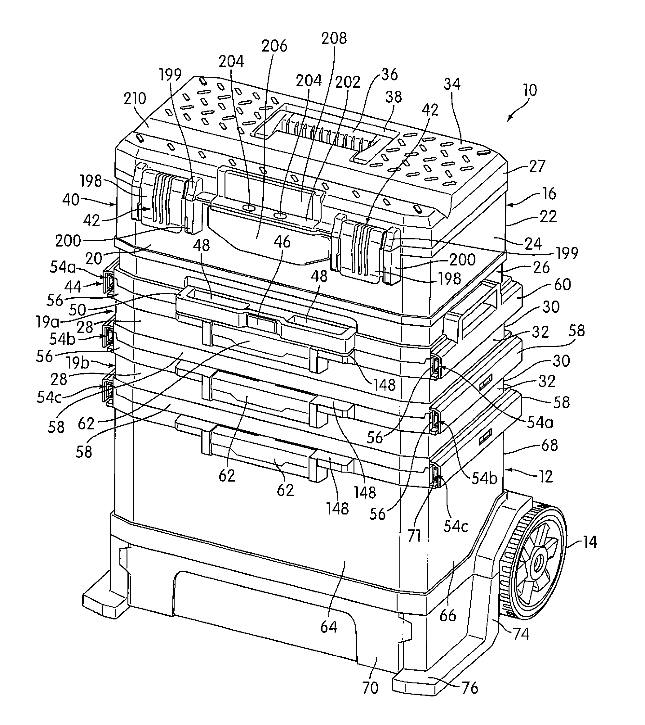
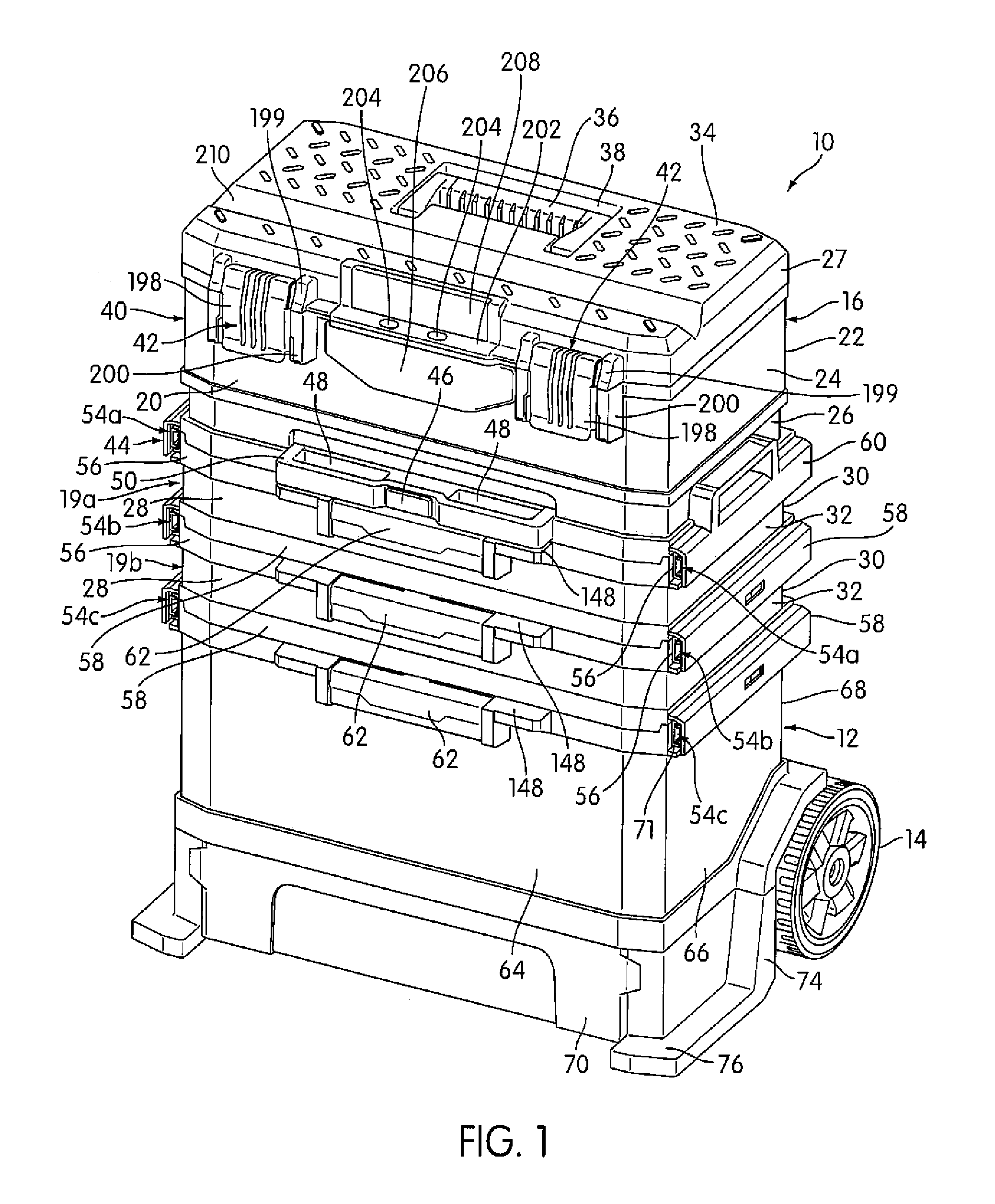
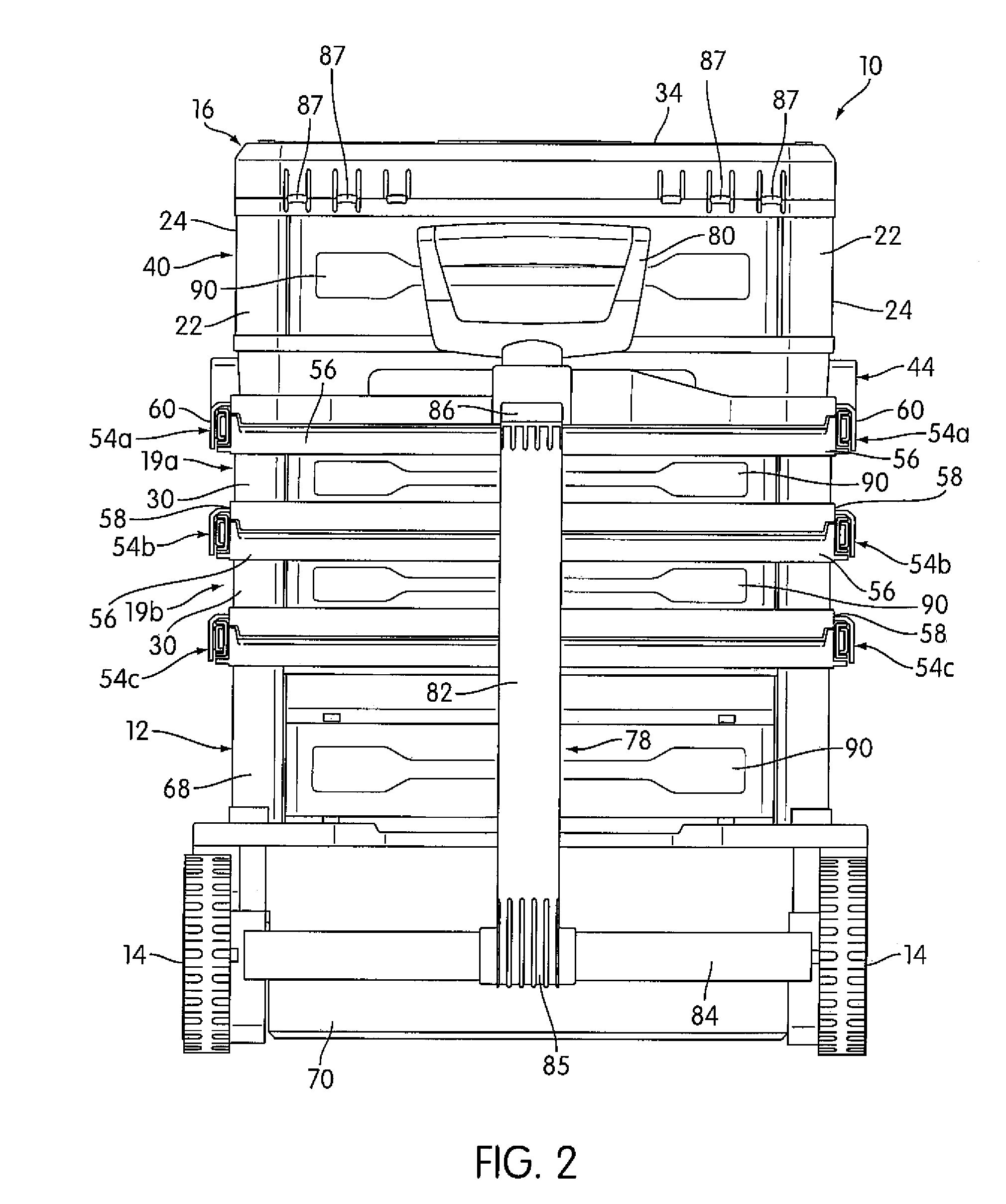
[0027]FIG. 1 shows a rolling container assembly 10 in accordance with an embodiment of the present invention. The apparatus includes a base container 12, a removable container 16 having a container portion 40 and a lid 34 pivotally attached to the container portion 40, a container engaging region 44 on which the removable container 16 is engaged, and a manually engageable pulling handle 80 (shown in FIG. 2). The embodiment of FIG. 1 also includes two rotatable ground engaging wheels 14 (although only one can be seen in FIG. 1) mounted toward the bottom of the rolling container assembly 10 for rotation about an axis to provide rolling support for the rolling container assembly 10. The number and configuration of wheels 14 is not intended to be limiting, and other embodiments may have more or fewer wheels 14 and in different locations on the rolling container assembly 10. The wheels 14 may have treads on its outer surface and may be fabricated of rubber or other anti-slip material.

[00...


PUM


Abstract

A rolling container assembly includes a base container, wheels to provide rolling support, at least one removable container, and a container engaging region with an automatic lock interacting between the removable container and the container engaging region. The automatic lock is releasable so that the removable container can be released to enable the at least one removable container to be carried by its carrying handle and transported separately from the base container. The assembly has a lower drawer and an upper drawer, and a slide structure having a first portion mounted to the upper drawer and a second portion mounted to the lower drawer to facilitate movement of the drawers. The lower drawer and upper drawer are independently movable between their respective open and closed positions. The apparatus includes a central frame structure carrying a lock member that enables the upper drawer to be locked in the closed position.

Description

FIELD OF THE INVENTION[0001]The present invention relates to a rolling container assembly.BACKGROUND OF THE INVENTION[0002]Rolling tool container assemblies are commonly used to carry a plurality of working tools to the working location. However, such tool container assemblies typically have side walls that contribute to the weight of the assembly or have drawers that cannot be moved independently. Tool container assemblies also typically do not have removable storage containers that are easily connectable after being removed. There is a need in the art for an improved storage system.SUMMARY OF THE INVENTION[0003]One aspect of this invention provides an apparatus for transporting articles between working locations. The apparatus includes a base container having an interior space in which articles to be transported can be stored and one or more rotatable ground engaging wheels mounted towards the bottom of the apparatus for rotation about an axis to provide rolling support for the ap...

Claims


Application Information

Patent Timeline
Patent Type & Authority Patents(United States)
IPC IPC(8): B62B1/00
CPCB25H3/028B25H3/027
Inventor LANDAU, EITANTWIG, NOAM
Owner THE STANLEY WORKS ISRAEL
Why Eureka
Try Eureka