Method for producing ink-jet head

a production method and ink jet technology, applied in printing, electrical equipment, basic electric elements, etc., can solve the problems of affecting affecting the ink drop ejection performance, and easy eroded, so as to improve the durability, and improve the durability of the ink-jet head.

Inactive Publication Date: 2012-03-13
FUJIFILM CORP
View PDF7 Cites 0 Cited by
  • Summary
  • Abstract
  • Description
  • Claims
  • Application Information

AI Technical Summary

Benefits of technology

[0008]However, when the nozzle portion, which contacts ink, of the nozzle plate is formed of silicon and the silicon surface contacts the ink, it is easily eroded by an alkaline component or the like in the ink. This may affect the ink drop ejection performance, and, consequently, affect the durability of the ink-jet head.
[0009]In the above configuration of a conventional ink jet head, the inorganic oxide is formed in a separated form and exists only in an island-like state. Therefore, contact between the inner wall surface of the nozzle hole and the ink cannot be prevented and, since the inner wall contacts the ink, it is difficult to suppress or avoid erosion of the wall surface.

Problems solved by technology

However, when the nozzle portion, which contacts ink, of the nozzle plate is formed of silicon and the silicon surface contacts the ink, it is easily eroded by an alkaline component or the like in the ink.
This may affect the ink drop ejection performance, and, consequently, affect the durability of the ink-jet head.
Therefore, contact between the inner wall surface of the nozzle hole and the ink cannot be prevented and, since the inner wall contacts the ink, it is difficult to suppress or avoid erosion of the wall surface.

Method used


Image

  • Method for producing ink-jet head
  • Method for producing ink-jet head
  • Method for producing ink-jet head

Examples


Embodiment Construction

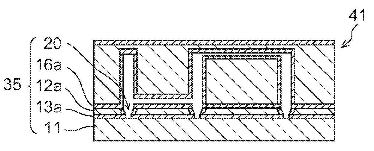
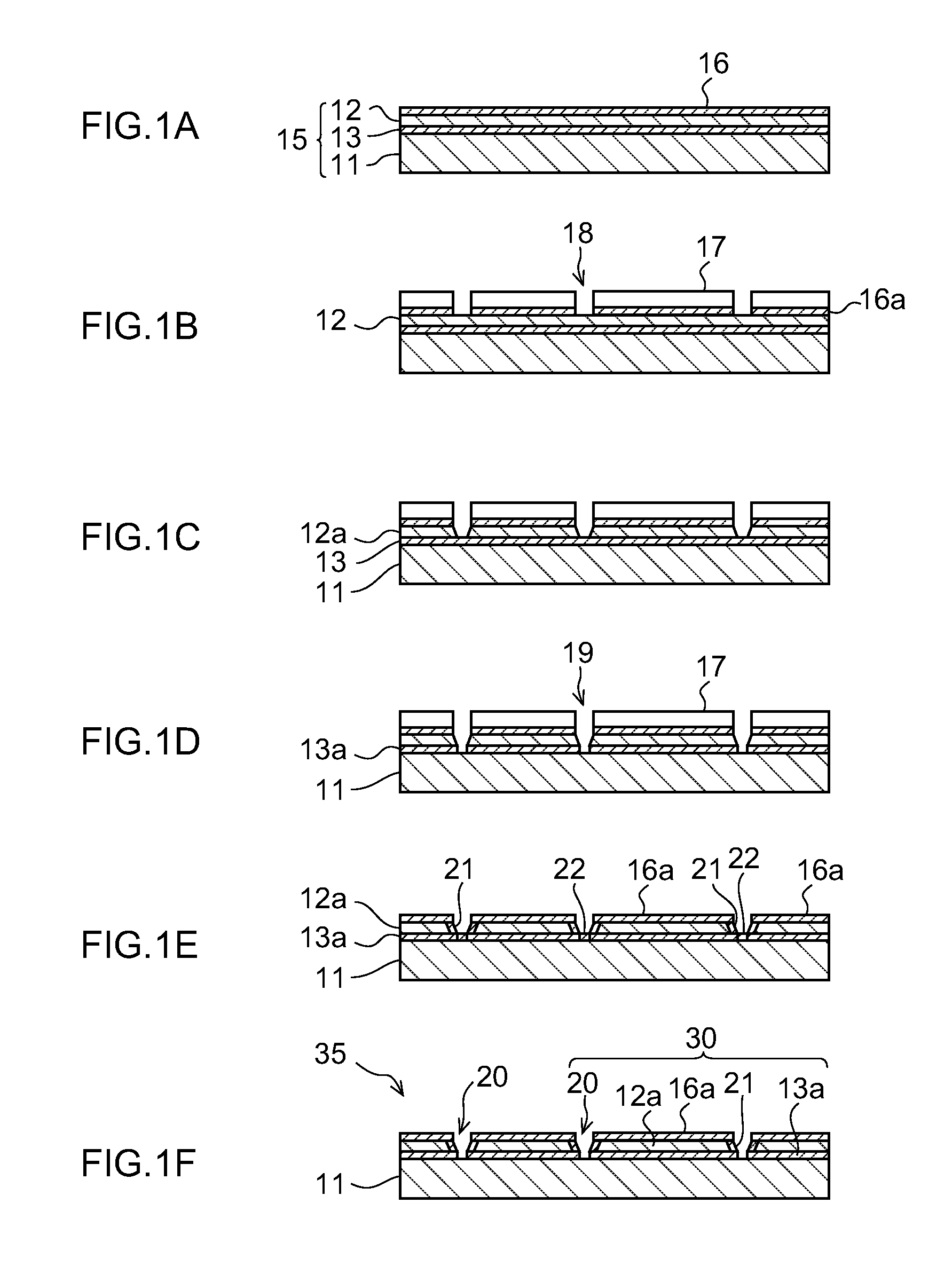
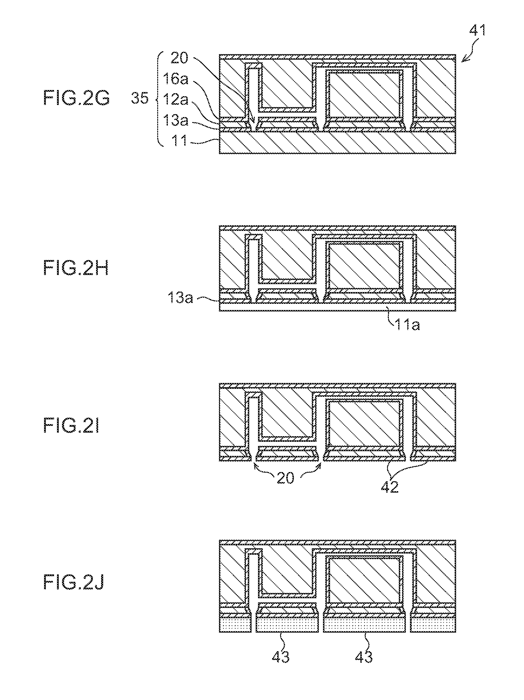
[0014]A method for producing an ink jet head of the present invention includes: first oxidizing in which, in an SOI substrate having a first SiO2 layer between two Si layers (a first Si layer and a second Si layer), among the two Si layer (the first Si layer and the second Si layer), at least the first Si layer is thermally oxidized to form a second SiO2 layer (first oxidizing process); forming a nozzle hole by removing a part of the second SiO2 layer and a part of the first Si layer between the first SiO2 layer and the second SiO2 layer, by performing an etching treatment until at least the first SiO2 layer is exposed (nozzle hole formation process); second oxidizing in which a side wall of at least the first Si layer in the formed nozzle hole is thermally oxidized to form an SiO2 layer (second oxidizing process); opening the nozzle hole by subjecting the SiO2 layers in the nozzle hole other than at the side wall to an anisotropic dry etching treatment until at least the second Si ...


PUM

PropertyMeasurementUnit
thicknessaaaaaaaaaa
thicknessaaaaaaaaaa
thicknessaaaaaaaaaa

Abstract

There is provided a method for producing an ink jet head. The method includes: first oxidizing in which, in an SOI substrate having a first SiO2 layer between a first Si layer and a second Si layer, among the first Si layer and the second Si layer, at least the first Si layer is thermally oxidized to form a second SiO2 layer; forming a nozzle hole by removing a part of the second SiO2 layer and a part of the first Si layer between the first SiO2 layer and the second SiO2 layer, by performing an etching treatment until at least the first SiO2 layer is exposed; second oxidizing in which a side wall of at least the first Si layer in the formed nozzle hole is thermally oxidized to form an SiO2 layer; opening the nozzle hole by subjecting the SiO2 layers in the nozzle hole other than at the side wall to an anisotropic dry etching treatment until at least the second Si layer is exposed; and forming a nozzle by removing the second Si layer.

Description

CROSS-REFERENCE TO RELATED APPLICATION[0001]This Application claims priority under 35 USC 119 from Japanese Patent Application No. 2009-061356, filed on Mar. 13, 2009, the disclosure of which is incorporated by reference herein.BACKGROUND OF THE INVENTION[0002]1. Technical Field[0003]The present invention relates to a method for producing an ink jet head that ejects ink.[0004]2. Description of the Related Art[0005]An ink jet head provided in an image recording apparatus such as a printer or a copier performs recording by ejecting ink drops from an ejection nozzle that ejects the ink. Therefore, the form or accuracy of the nozzle, or changes therein over time, greatly influence the ink drop ejection performance.[0006]In addition, the surface of a member forming the nozzle hole may influence the ink drop ejection performance depending on the properties thereof or changes therein over time.[0007]As ink jet heads, in general, those in which a nozzle portion of a nozzle plate is formed u...

Claims


Application Information

Patent Timeline
Patent Type & Authority Patents(United States)
IPC IPC(8): H01L21/76
CPCB41J2/161B41J2/1628B41J2/1629B41J2/1631B41J2/1632B41J2/164
Inventor OHSHIBA, HISASHI
Owner FUJIFILM CORP
Why Eureka
Try Eureka