
Copolymer, and liquid crystal alignment layer including cured product thereof

a liquid crystal alignment and copolymer technology, applied in the field of polymer, can solve the problems of reducing display luminance, affecting unable to control the alignment of liquid crystal molecules, etc., and achieves the effect of superior ability to control the alignment, efficient alignment property, and high voltage holding ratio

Active Publication Date: 2017-06-20
DAINIPPON INK & CHEM INC
View PDF34 Cites 0 Cited by
  • Summary
  • Abstract
  • Description
  • Claims
  • Application Information

AI Technical Summary

Benefits of technology

[0051]By using the polymer of the present invention, a liquid crystal alignment layer which has a superior ability to control the alignment of the liquid crystals and the pretilt angles, and a high voltage holding ratio (VHR) can be produced, which is efficiently provided with an alignment property at a low dose of irradiation of polarized light. Further, a liquid crystal alignment layer having excellent coatability, in addition to the characteristics above, and / or a liquid crystal alignment layer having low residual voltage can be produced.
[0052]Since the liquid crystal alignment layer of the present invention has a high voltage holding ratio (VHR) and a superior ability to control the alignment of the liquid crystals and the pretilt angles, and is not easily eroded by a solvent or the like, it can be used to efficiently produce a liquid crystal display element and a liquid crystal display device, each exhibiting excellent display properties and reliability. Further, the optical anisotropic body of the present invention is useful for the production of an optical anisotropy film that can be used in optical compensation or the like.

Problems solved by technology

However, since it cannot be said that the liquid crystal display device using a liquid crystal layer of a vertical alignment type necessarily has sufficient viewing angle characteristics, various methods have been investigated to improve the viewing angle characteristics.
However, with the use of the slit or the rib, the slit or the rib is linear unlike a case where a pretilt direction is defined by inserting liquid crystal molecules into two alignment films used in a TN mode used in the related art, and thus, the ability to control the alignment for the liquid crystal molecules becomes uneven within a pixel, whereby a problem of generation of a distribution in the response speeds arises.
In addition, there is another problem that a region provided with a slit or a rib exhibits decreased optical transmittance, resulting in a decrease in display luminance.
However, this method faces a problem such as changes in characteristics caused by the addition of monomers in the liquid crystal material, difficulty in controlling the process, and adverse effects of the residual monomers.
However, it is difficult to form a precise alignment division structure by the rubbing method, and thus problems of static electricity caused by friction and generation of impurities arise.
However, when a horizontal alignment treatment is carried out by a rubbing treatment with a polyimide alignment film, the pretilt angle provided to the liquid crystal molecules exceeds one degree, and thus, a problem that the display characteristics are deteriorated arises.
However, the photo-alignment method using these compounds has a problem such as a low voltage holding ratio (VHR), as compared with a case using an ordinary alignment film.
It also has problems such as a high residual voltage (RDC) caused by residual charges and frequent occurrence of seizure.
However, since the photo-alignment layer using a compound having an azo group is a low-molecular-weight compound, there may occur problems in a step of producing a liquid crystal cell, for example, it is flown off in a washing step or eroded by an adhesive member such as a sealing agent, in some cases.
However, the photo-alignment layer formed with a compound having a photochemically crosslinkable site, such as a cinnamic acid derivative, is poor at sensitivity, as compared with a compound having an azo group, is required to be irradiated with light having a potent anisotropic property during the photo-alignment, and thus, is not easily commercialized due to large-scale devices needed.
However, in the cited document, the polymer compound is used as an optical non-linear polymer, there is no suggestion of use as an optical anisotropic body, and it was not clear how to use specifically and what kind of characteristics the compound has.

Method used


Image

  • Copolymer, and liquid crystal alignment layer including cured product thereof
  • Copolymer, and liquid crystal alignment layer including cured product thereof
  • Copolymer, and liquid crystal alignment layer including cured product thereof

Examples


example 1

[0428]0.34 parts (0.5 mmol) of a compound represented by the formula (P-1), and 9.66 (9.5 mmol) of a compound represented by the formula (Cinv-1) were dissolved in 10 parts of ethyl methyl ketone to give a solution 1, and 0.01 parts of azobisisobutyronitrile (AIBN) was added to the solution 1. The mixture was heated and refluxed for 2 days under a nitrogen atmosphere to give a solution 2. Next, the solution 2 was added dropwise to 60 parts of methanol under stirring, and the precipitated solid was filtered. The obtained solid was dissolved in 5 parts of tetrahydrofuran (THF), 120 parts of ice-cooled hexane was added dropwise thereto under stirring, and the precipitated solid was filtered. The obtained solid was dissolved in 5 parts of THF, added dropwise to 120 parts of ice-cooled methanol under stirring, and the precipitated solid was filtered. The obtained solid was dissolved in THF and dried under vacuum to obtain a copolymer (ACv-1).

[0429](Preparation of Copolymers (ACv-2) to (A...

example 15

[0440]The copolymer (ACv-1) was dissolved in cyclopentanone to be 0.8% and the solution was stirred at room temperature for 10 minutes. Then, the solution was applied onto a glass plate as a substrate at 2000 rpm for 30 seconds, using a spin coater, and dried at 100° C. for 3 minutes. Then, the surface was visually observed and as a result, it was found that a polymer was uniformly applied on the glass plate to form a smooth film.

[0441]Next, irradiation of linear polarized and parallel light of visible ultraviolet light (wavelength: 365 nm, irradiation intensity: 10 mW / cm2) was performed onto the coated glass plate as a substrate using an ultrahigh-pressure mercury lamp via a wavelength cut filter, a band-pass filter, and a polarizing filter in a direction of 45 degrees with respect to the substrate. The irradiation dose was 100 mJ / cm2.

[0442]A liquid crystal cell was fabricated by using the coated glass plate prepared by the method above. The gap between the plates was set to 10 μm ...

example 29

[0478]The copolymer (ACv-1) was dissolved in N-methylpyrrolidone (NMP) to be 0.5%, and the solution was stirred at room temperature for 10 minutes. The solution was then applied to a glass plate serving as a substrate by using a spin coater and dried at 100° C. for 30 minutes.

[0479]Next, irradiation of linear polarized and parallel light of visible ultraviolet light (wavelength: 365 nm, irradiation intensity: 20 mW / cm2) was performed onto the coated glass plate as a substrate using an ultrahigh-pressure mercury lamp via a wavelength cut filter, a band-pass filter, and a polarizing filter in a direction of 45 degrees with respect to the substrate. The irradiation dose was 90 mJ / cm2.

[0480]The polymerizable liquid crystal composition (LC-1) was applied onto the obtained alignment layer, using a spin coater, and dried at 80° C. for 1 minute. Then, (LC-1) was polymerized by irradiation of ultraviolet rays at 1 J / cm2 under a nitrogen atmosphere to obtain an optical anisotropic body.

[0481]...


PUM

PropertyMeasurementUnit
pretilt angleaaaaaaaaaa
temperatureaaaaaaaaaa

Abstract

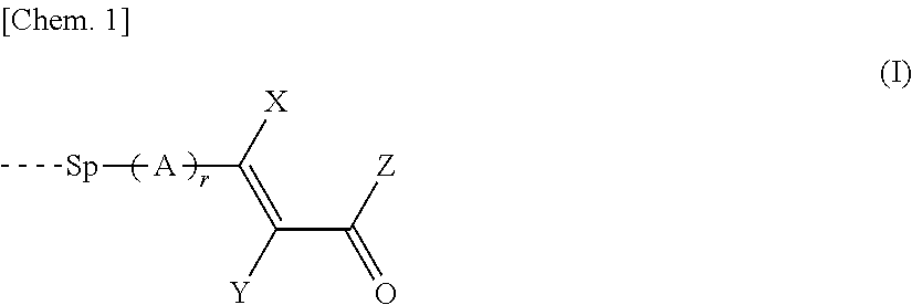
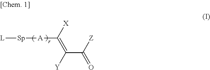
Provided is a liquid crystal alignment layer of which a constituent member is a polymer represented by the general formula (I).

Description

TECHNICAL FIELD[0001]The present invention relates to a polymer, a liquid crystal alignment layer, a liquid crystal display element, and an optical anisotropic body. More specifically, the present invention relates to a liquid crystal display element, a liquid crystal alignment layer in the liquid crystal display element, a polymer for producing the liquid crystal alignment layer, and an optical anisotropic body useful for an optical anisotropy film used in optical compensation of a liquid crystal display element, or the like.[0002]The present application claims priority based on Japanese Patent Application Nos. 2011-146556, 2011-146637, and 2011-146638, each filed on Jun. 30, 2011, the contents of which are incorporated herein by reference.BACKGROUND ART[0003]An alignment layer for aligning liquid crystals is important for keeping the order of alignment of the liquid crystals and realizing optical characteristics based on refractive index anisotropy of liquid crystal molecules, and...

Claims


Application Information

Patent Timeline
Patent Type & Authority Patents(United States)
IPC IPC(8): C09K19/38C08F220/36C08F220/30C08F220/10G02F1/1337C08F222/10C08F220/24
CPCG02F1/133711C08F220/10C08F220/30C08F220/36C09K19/3852C08F220/24C08F2220/305C08F2222/102C08F220/305C08F222/1025C08F222/404C08F220/365C08F220/303C08F220/58C08F220/1818G02F1/1337
Inventor SCHADT, MARTINCHIGRINOV, VLADIMIR GRIGORIEVICHKWOK, HOI-SINGNOSE, SAYAKAIWAKUBO, MASAYUKIHAYASHI, MASANAONAGASHIMA, YUTAKANISHIYAMA, ISATAKATSU, HARUYOSHI
Owner DAINIPPON INK & CHEM INC
Learn More