Busbar pack

a busbar pack and pack body technology, applied in the field of busbar packs, can solve the problems of high thermal load or overload, inability to inability to adequately cool down the busbar pack, etc., and achieve the effect of reducing the thermal load

Active Publication Date: 2012-03-13
SIEMENS AG
View PDF17 Cites 13 Cited by
  • Summary
  • Abstract
  • Description
  • Claims
  • Application Information

AI Technical Summary

Benefits of technology

[0012]Independently of the function of the two bars which are in the form of meshes of at least one inner busbar in the busbar pack, these bars which are in the form of meshes may be composed of electrically insulating material or electrically conductive material. If they are composed of electrically conductive material, then a portion of the current of this inner busbar can also flow via the bar which is in the form of a mesh. This reduces the thermal load on this inner busbar.

Problems solved by technology

If other components of the converter are fitted around this busbar pack because of a shortage of space in the interior of the converter, then this busbar pack cannot be cooled, or cannot be adequately cooled, by air convection.
The parts of the busbar pack, for example the isolating bars and their screws, are therefore thermally highly loaded or overloaded, as a result of which the busbar pack could fail as a result of excessive thermal loading.
This disadvantage could be overcome by the use of high-temperature-resistant parts composed of insulating material, but these cannot be used for cost reasons.

Method used


Image

  • Busbar pack
  • Busbar pack
  • Busbar pack

Examples


Embodiment Construction

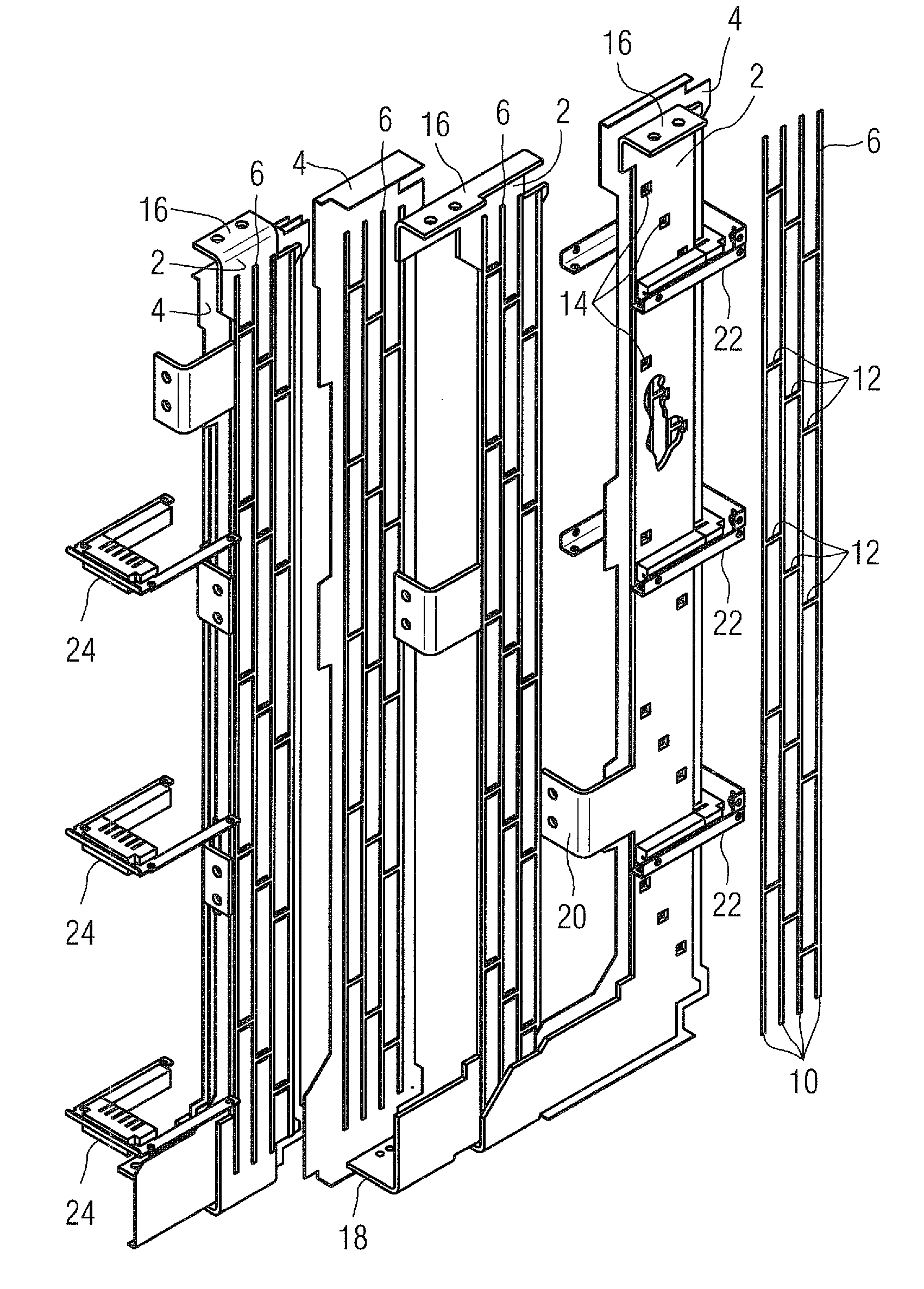
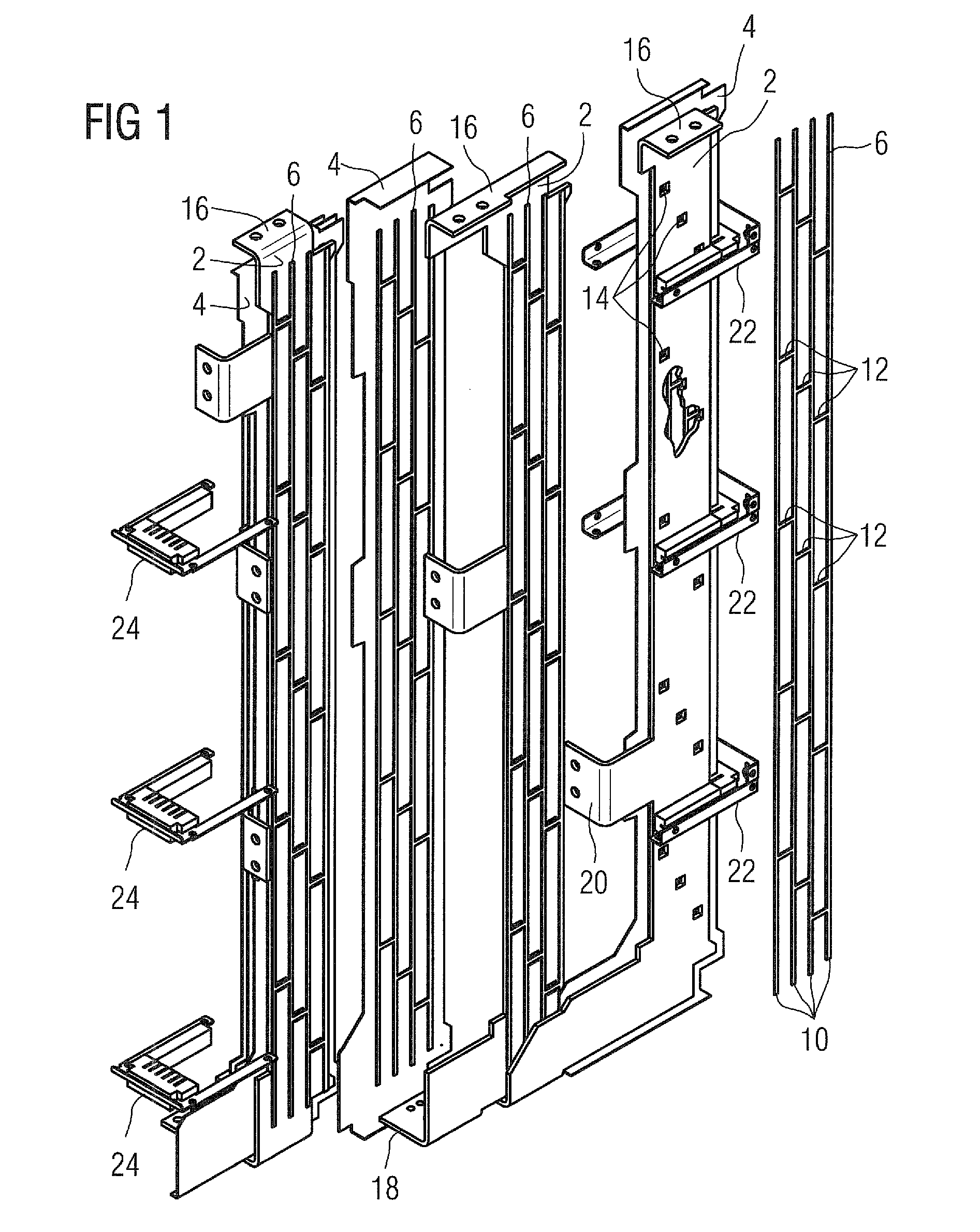
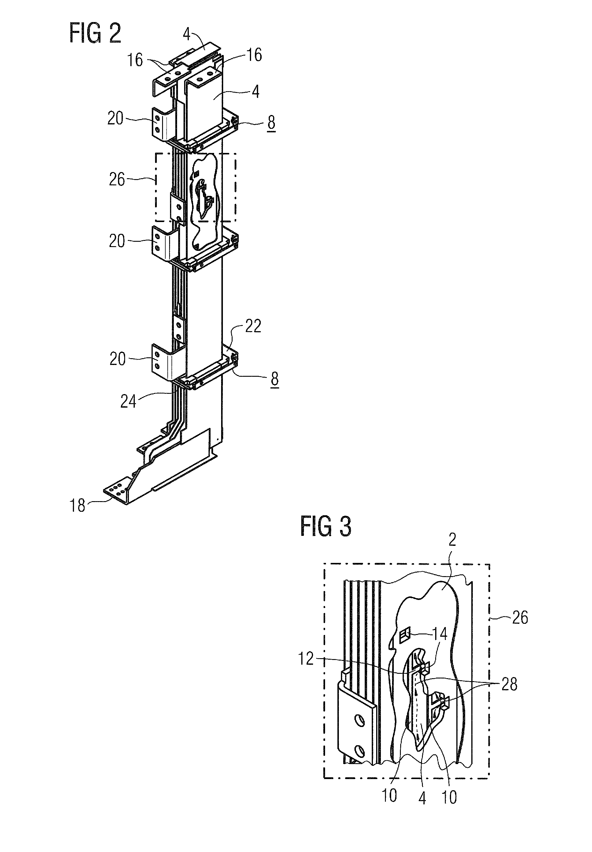
[0018]In FIG. 1, 2 denotes a busbar, 4 an isolating bar, 6 a bar which is in the form of a mesh and 8 a two-part apparatus. As can be seen from this illustration, each bar 6 which is in the form of a mesh is arranged on a flat face of each busbar 2. This means that each busbar 2 is provided with bars 6 which are in the form of meshes on both sides. In order to keep the complexity for cooling the busbar pack as low as possible, it is sufficient for only one inner busbar 2 in the busbar pack to be provided with bars 6 which are in the form of meshes, on both sides. This means that, in the case of a three-phase busbar pack, only the inner busbar 2 of this busbar pack is provided with the additional bars 6 which are in the form of meshes. The illustrated bars 6 which are in the form of meshes in this illustration have four longitudinal webs 10 and fifteen transverse webs 12. These transverse webs 12 separate the longitudinal webs 10 from one another. With four longitudinal webs 10, thre...


PUM


Abstract

The invention relates to a busbar pack comprising n busbars (2) and at least n−1 insulating bars (4) the surfaces of which project beyond the busbars (2), one insulating bar (4) being interposed between two busbars (2), said stack of bars (2, 4) being immobilized in their position relative each other by devices. The invention is characterized in that at least one inner busbar (2) is provided with a reticular bar (6) on both sides thereof and has perforations (14) that are arranged to match crossbars (12) of corresponding reticular bars (6). The invention allows production of a busbar pack at least the inner busbar (2) of which is convection-cooled, said busbar cooling system being producible at low costs.

Description

CROSS-REFERENCES TO RELATED APPLICATIONS[0001]This application is the U.S. National Stage of International Application No. PCT / EP2007 / 061195, filed Oct. 19, 2007, which designated the United States and has been published as International Publication No. WO 2008 / 071493 and which claims the priority of German Patent Application, Serial No. 10 2006 058 327.2, filed Dec. 11, 2006, pursuant to 35 U.S.C. 119(a)-(d).BACKGROUND OF THE INVENTION[0002]The invention relates to a busbar pack.[0003]Busbars are accommodated in commercially available converters. Up to three busbars, in particular busbars with thin surfaces, are physically isolated from one another in these busbar packs by means of isolating bars, for example plastic bars. These seven bars are combined to form a pack by means of apparatuses, for example screws. This busbar pack is advantageously accommodated and connected at an airy or ventilated installation location in the converter. If other components of the converter are fitte...

Claims


Application Information

Patent Timeline
Patent Type & Authority Patents(United States)
IPC IPC(8): H05K1/02H02B1/20
CPCH02B1/20H02B1/565
Inventor HIRSCHFELD, THOMAS
Owner SIEMENS AG
Why Eureka
Try Eureka