

Electrostatic connector
a technology of electrostatic connectors and connectors, applied in the direction of coupling device connections, waveguide devices, coupling parts engagement/disengagement, etc., can solve problems such as electrical contacts deterioration
- Summary
- Abstract
- Description
- Claims
- Application Information
AI Technical Summary
Benefits of technology
Problems solved by technology
Method used
Image

Examples
embodiment 1
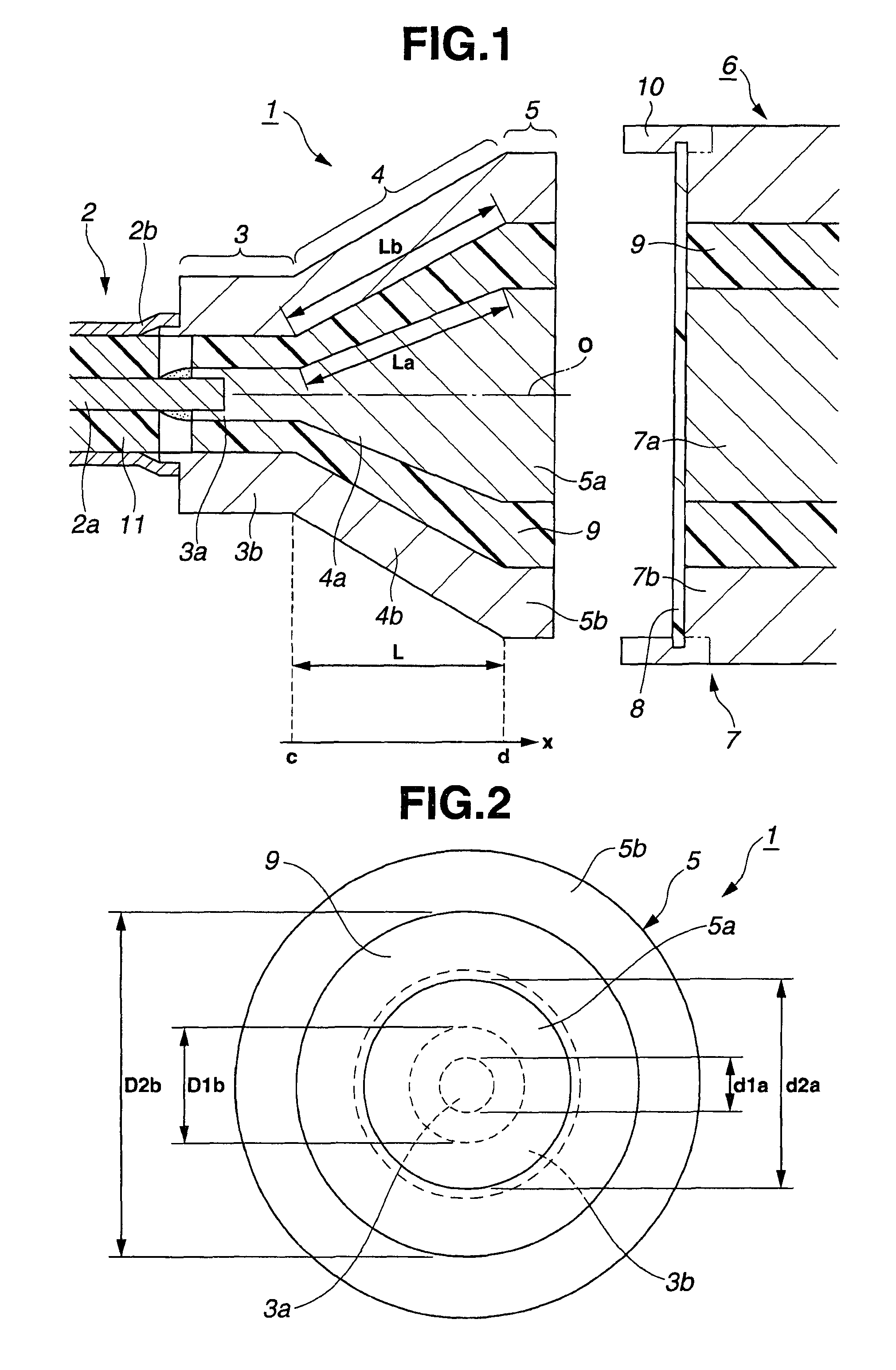
[0035]FIGS. 1 and 2 relate to an embodiment 1 of the present invention. FIG. 1 shows the structure of an electrostatic coupling connector which is the embodiment 1 of the connector of the present invention in a vertical sectional view. FIG. 2 shows a front view seeing the structure of the electrostatic coupling connector from the electrode portion side.
[0036]As shown in FIG. 1, an electrostatic coupling connector 1 of the embodiment 1 of the present invention has a first conductor portion 3 formed on the proximal end side thereof connected to one end of a coaxial cable 2. Signals transmitted from the other end of the coaxial cable 2 to the one end of the same are transmitted via a second conductor portion 4 electrically connected to the first conductor portion 3 to an electrode portion 5 provided on an end portion of the second conductor portion 4.
[0037]Here, the first conductor portion 3, the second conductor portion 4 and the electrode portion 5 are formed integrally using metal s...
embodiment 2
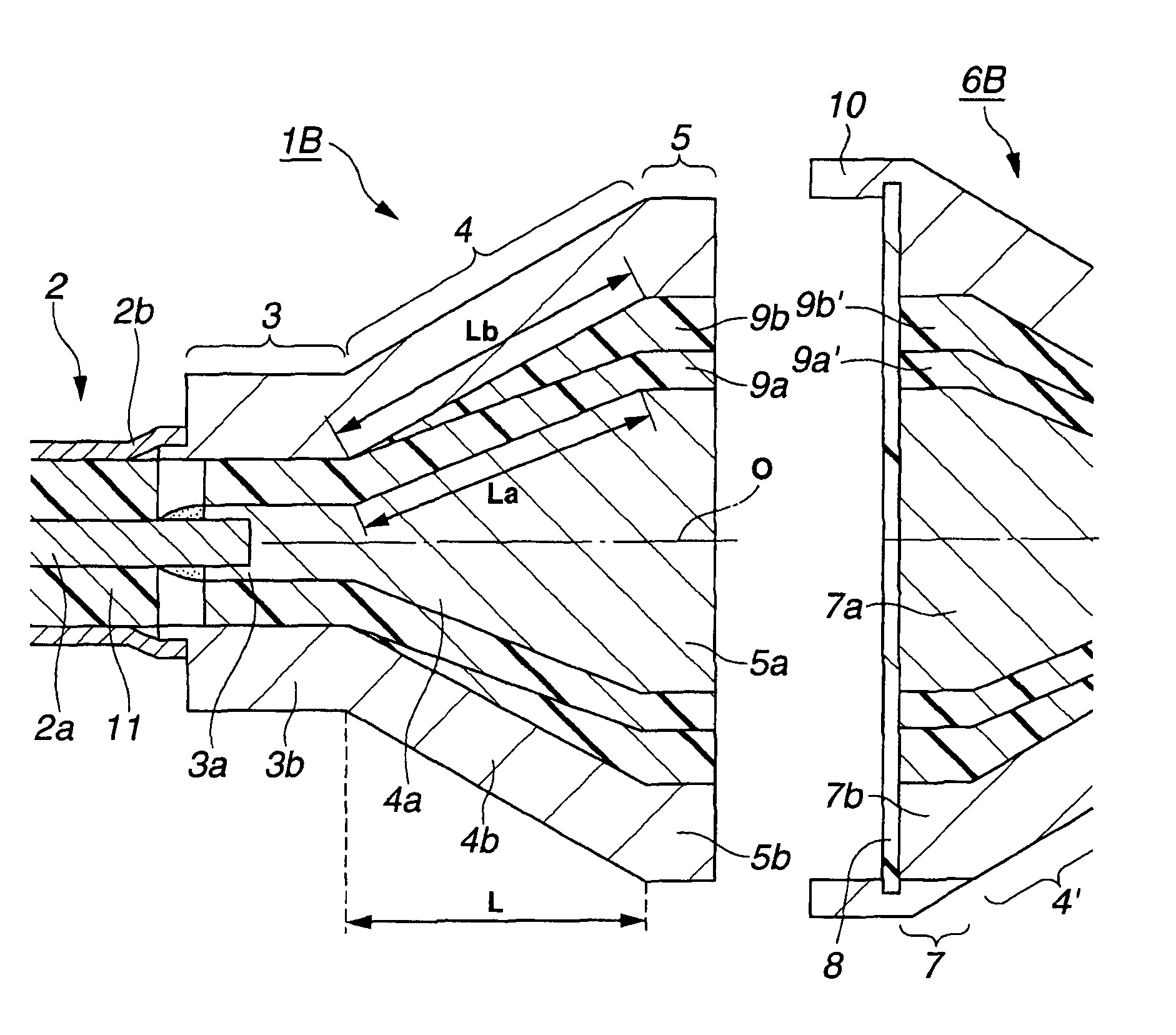
[0080]FIG. 3 shows an electrostatic coupling connector 1B of an embodiment 2 of the present invention. The electrostatic coupling connector 1 of the embodiment 1 has a structure in which a dielectric 9 having one relative dielectric constant (value) is filled between the inner conductor portion and the outer conductor portion.
[0081]On the other hand, in the electrostatic coupling connector 1B of the present embodiment, dielectrics 9a, 9b of different relative dielectric constants εa, εb are filled at least between the inner second conductor portion 4a and the outer second conductor portion 4b in the second conductor portion 4.
[0082]In this case, the setting is such that the relative dielectric constant εb of the dielectric 9b which is filled so as to contact with the inner surface of the outer second conductor portion 4b is smaller than the relative dielectric constant εa of the dielectric 9a which is filled so as to contact with the outer surface of the inner second conductor porti...
embodiment 3
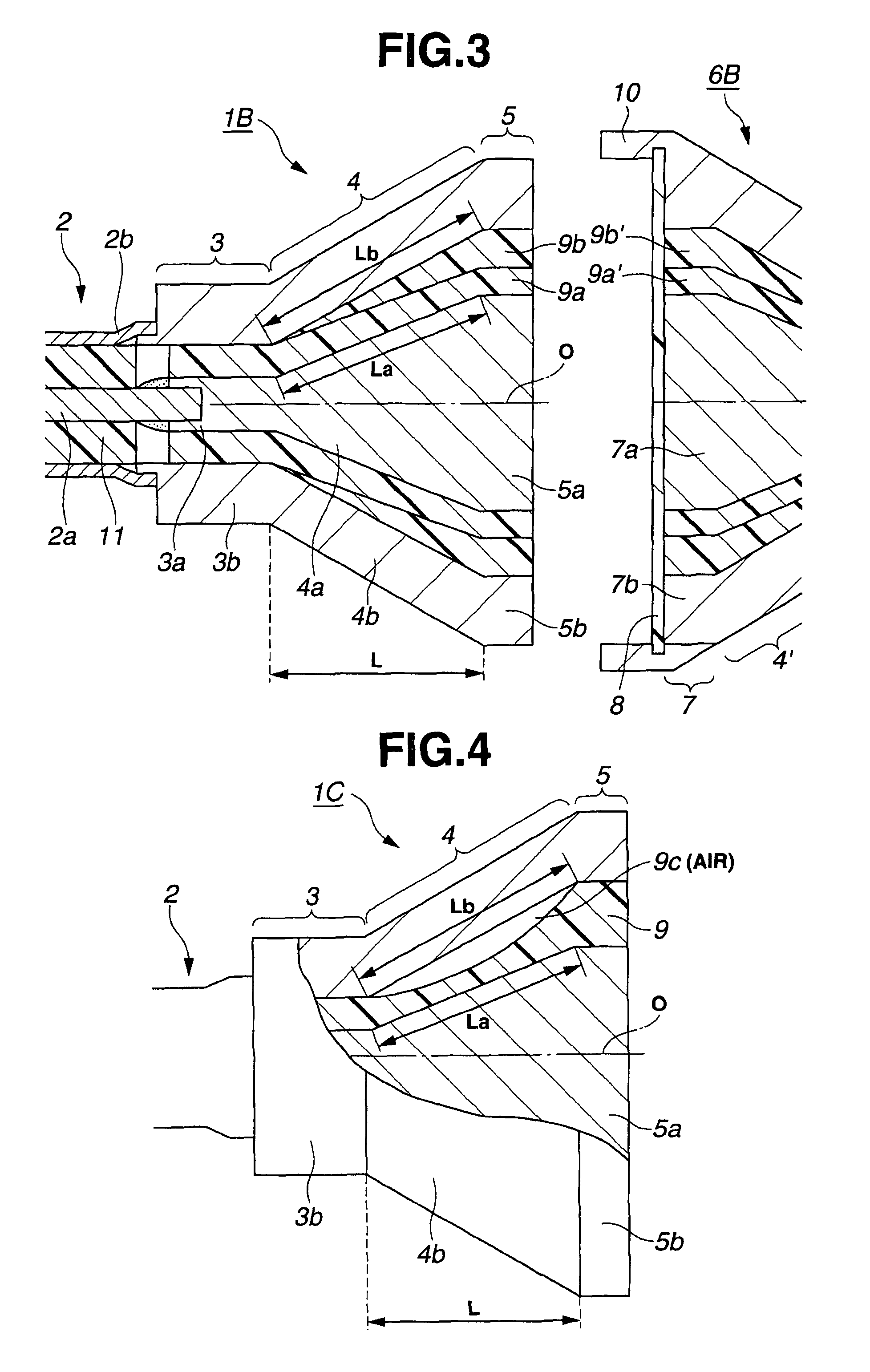
[0097]FIG. 5 shows an electrostatic coupling connector 1D of an embodiment 3 of the present invention. The electrostatic coupling connector 1D of the present embodiment has a structure similar to the electrostatic coupling connector 1 of an embodiment 1 up to the midway portion of the second conductor portion 4 in the first conductor portion 3 side of the second conductor portion 4.
[0098]In the portion which is in the electrode portion 5 side of the midway position (also referred to as the boundary position), a dielectric 9d having a dielectric constant smaller than the dielectric 9 used in the first conductor portion 3 side is filled between the inner second conductor portion 4a and the outer second conductor portion 4b in the second conductor portion 4, for example.
[0099]In this case, the dielectric 9d may be air. In this case, there may be no filling between the inner second conductor portion 4a and the outer second conductor portion 4b.
[0100]In addition, in the vicinity of the ...
PUM
 Abstract
Description
Claims
Application Information