Zoom lens system and image pickup apparatus including the zoom lens system

a zoom lens and zoom technology, applied in the field of zoom lens system and image pickup apparatus including the zoom lens system, can solve the problems of coma at the telephoto end, difficult to excellently correct chromatic aberration, spherical aberration, etc., and achieve excellent optical performance and excellent correction

Inactive Publication Date: 2012-03-13
CANON KK
View PDF18 Cites 7 Cited by
  • Summary
  • Abstract
  • Description
  • Claims
  • Application Information

AI Technical Summary

Benefits of technology

[0009]According to the present invention, chromatic aberration, spherical aberration, and coma may be excellently corrected in a balanced manner, and hence a zoom lens system having excellent optical performance over the entire zoom range is obtained.

Problems solved by technology

However, a normal optical material having low dispersion and anomalous dispersion has a low refractive index as in a typical case of fluorite.
Thus, when only the optical material having low dispersion and anomalous dispersion or only a resin material having a low refractive index is used, it is difficult to excellently correct chromatic aberration, spherical aberration, and coma at the telephoto end.

Method used


Image

  • Zoom lens system and image pickup apparatus including the zoom lens system
  • Zoom lens system and image pickup apparatus including the zoom lens system
  • Zoom lens system and image pickup apparatus including the zoom lens system

Examples


embodiment 5

[0037]In Embodiment 5, the rear lens group LR includes the third lens unit B3 having a negative refractive power and the fourth lens unit B4 having a positive refractive power. In each of the embodiments, the number of lens units included in the rear lens group LR and the refractive power of each of the lens units are arbitrary and the rear lens group LR desirably includes at least two lens units. In each of the embodiments, in order to ensure a high zoom ratio (high magnification-varying ratio) and excellently correct aberrations, a lens unit having a positive refractive power and a lens unit having a negative refractive power are provided in order of from the object side to the image side. In each of the embodiments, the first lens unit B1 includes at least one negative lens. An Abbe number νd1n and a partial dispersion ratio θgF1n of a material of the at least one negative lens included in the first lens unit B1 satisfy the following conditions.

−1.68×10⁻³×νd1n+0.585<θgF1n<3...

embodiment 3

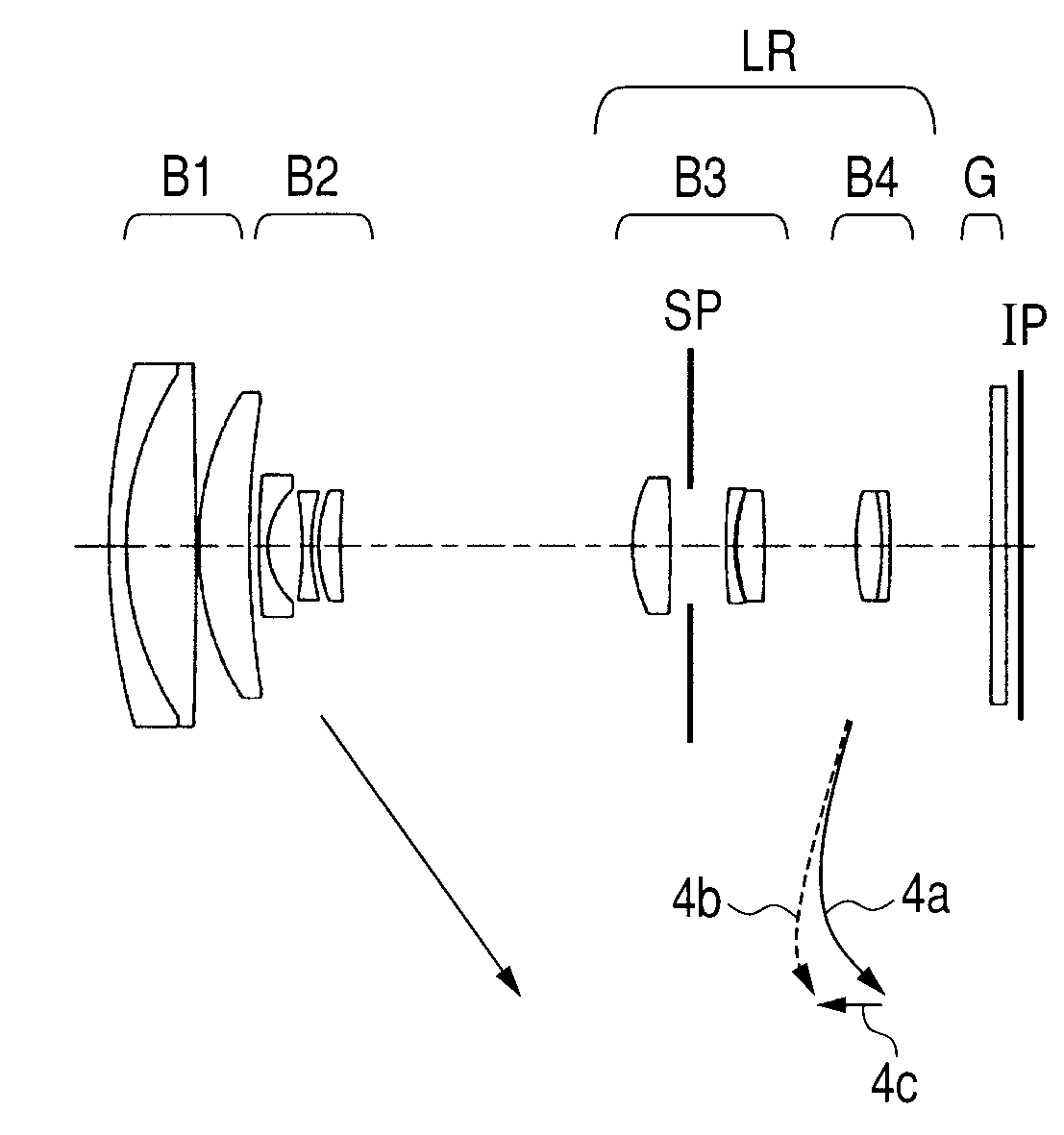
[0071]In Embodiment 3 illustrated in FIG. 5, during zooming from the wide angle end to the telephoto end, as illustrated by arrows, the first lens unit B1 moves to the object side and the second lens unit B2 moves to the image side. The third lens unit B3 nonlinearly moves to the object side. The fourth lens unit B4 moves along a locus convex to the object side to correct an image plane variation due to magnification varying. The aperture stop SP moves along a locus convex to the object side. The fourth lens unit B4 is moved on the optical axis to perform focusing.

[0072]In a case of focusing from the infinite-distance object to the near object at the telephoto end, as illustrated by an arrow 4c, the fourth lens unit B4 is moved to the object side. A solid curve 4a and a broken curve 4b with respect to the fourth lens unit B4 exhibit movement loci for correcting image plane variations due to zooming from the wide angle end to the telephoto end during focusing on the infinite-distance...

embodiment 4

[0073]In Embodiment 4 illustrated in FIG. 7, during zooming from the wide angle end to the telephoto end, as illustrated by arrows, the first lens unit B1 is moved to the object side and the second lens unit B2 is moved to the image side, to thereby perform main magnification varying. The third lens unit B3 and the fourth lens unit B4 move to the object side. The fifth lens unit B5 is moved along a nonlinear locus to correct a variation in image plane position due to the magnification varying. The aperture stop SP independently moves to the object side. A solid curve 5a and a broken curve 5b with respect to the fifth lens unit B5 exhibit movement loci for correcting image plane variations due to magnification varying from the wide angle end to the telephoto end during focusing on the infinite-distance object and during focusing on the near object, respectively. The fifth lens unit B5 is moved along the locus convex to the object side as described above, and hence the interval betwee...


PUM


Abstract

A zoom lens system, in which chromatic aberration, spherical aberration, and coma may be excellently corrected in a balanced manner so as to obtain excellent optical performance over an entire zoom range, includes, in order from an object side to an image side: a first lens unit having a positive refractive power; a second lens unit having a negative refractive power; and a rear lens group including a lens unit having a positive refractive power, in which: at least one of the first lens unit and the second lens unit is moved for zooming so that an interval therebetween at a telephoto end is larger than an interval at a wide angle end; the first lens unit includes at least one negative lens; and an Abbe number (νd1n) and a partial dispersion ratio (θgF1n) of a material of the at least one negative lens are appropriately set.

Description

BACKGROUND OF THE INVENTION[0001]1. Field of the Invention[0002]The present invention relates to a zoom lens system and an image pickup apparatus including the zoom lens system, and more particularly, to a zoom lens system and an image pickup apparatus including the zoom lens system, which are suitable for an image pickup optical system used for a still camera, a video camera, a digital still camera, a TV camera, or a monitoring camera.[0003]2. Description of the Related Art[0004]In recent years, the number of pixels of an image pickup element used for an image pickup apparatus such as a digital camera or a video camera has been increased. An image taking lens system used for the image pickup apparatus including the image pickup element is required to be a zoom lens system in which not only monochromatic aberrations such as spherical aberration and coma but also chromatic aberration are excellently corrected. A high zoom ratio is also required. In particular, a zoom lens system havi...

Claims


Application Information

Patent Timeline
Patent Type & Authority Patents(United States)
IPC IPC(8): G02B15/14
CPCG02B15/173G02B27/0062G02B15/143105
Inventor SAITO, SHINICHIROMIYAZAWA, NOBUYUKIKIMURA, TOMONORI
Owner CANON KK
Why Eureka
Try Eureka