Tire noise reduction device

a noise reduction device and tire technology, applied in the direction of wheels, inflatable tyres, vehicle components, etc., can solve the problems of time-consuming operation of sealing a hole in a punctured tire, inability to perform smooth tire sealing operation, and noise that is known to make the occupants of vehicles uncomfortable, so as to achieve the effect of retaining the durability of the noise absorption member

Active Publication Date: 2012-03-20
THE YOKOHAMA RUBBER CO LTD
View PDF11 Cites 12 Cited by
  • Summary
  • Abstract
  • Description
  • Claims
  • Application Information

AI Technical Summary

Benefits of technology

[0008]An object of the present invention is to provide a tire noise reduction device which allows rapid and reliable tire sealing when the tire runs over a nail or the like and is punctured, without deteriorating the durability of a noise absorbing member attached to the inner surface of a tread portion of a pneumatic tire.
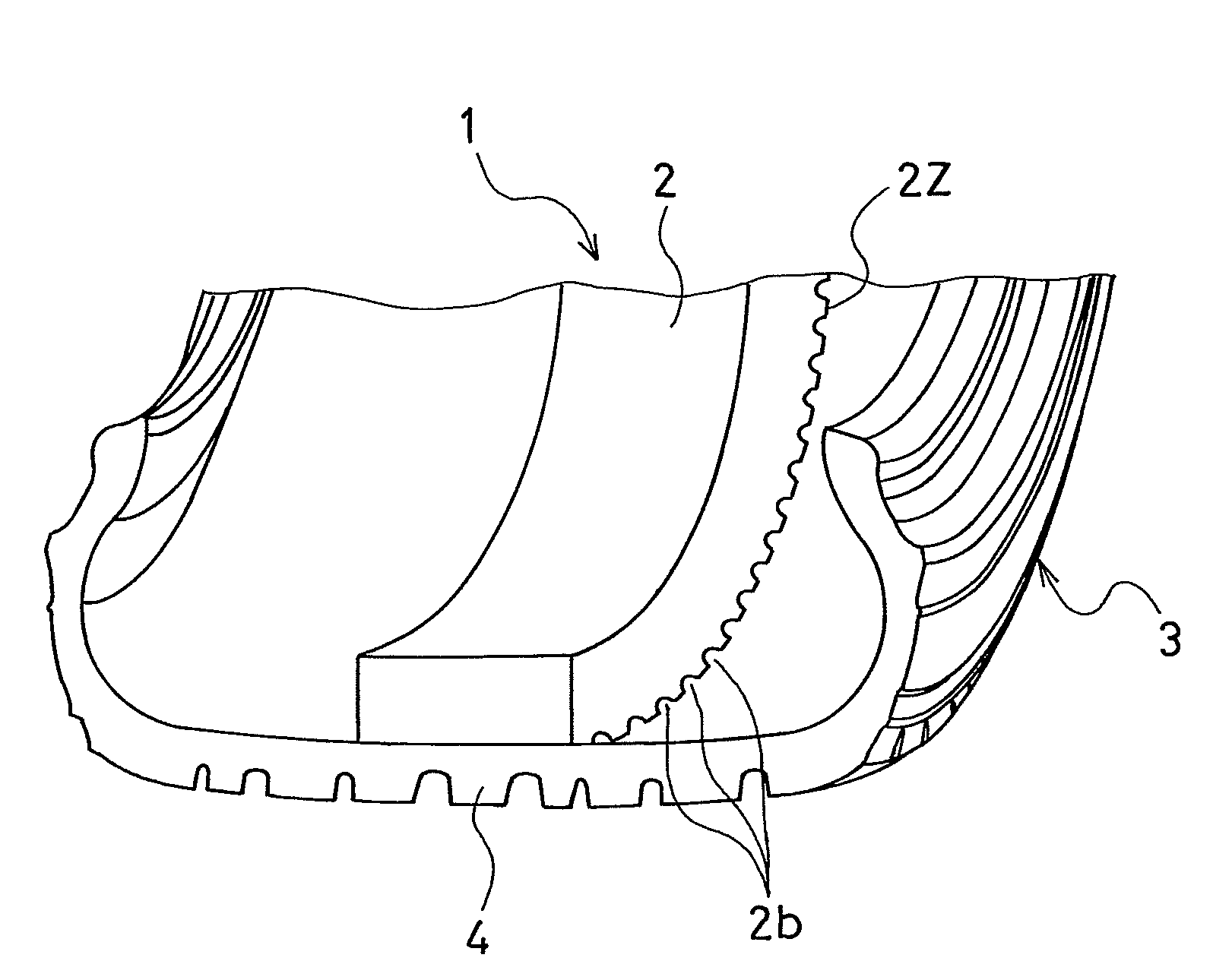
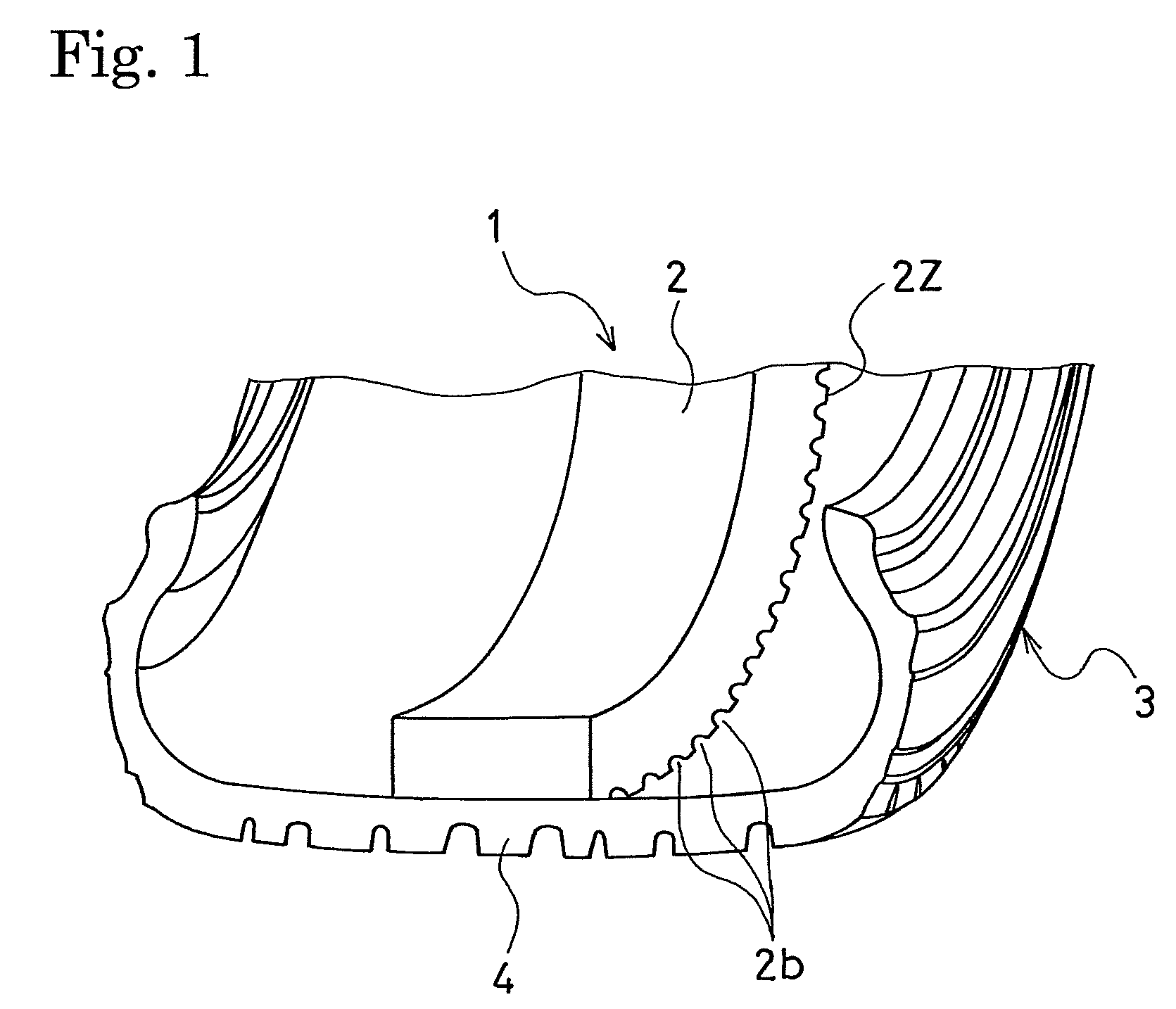
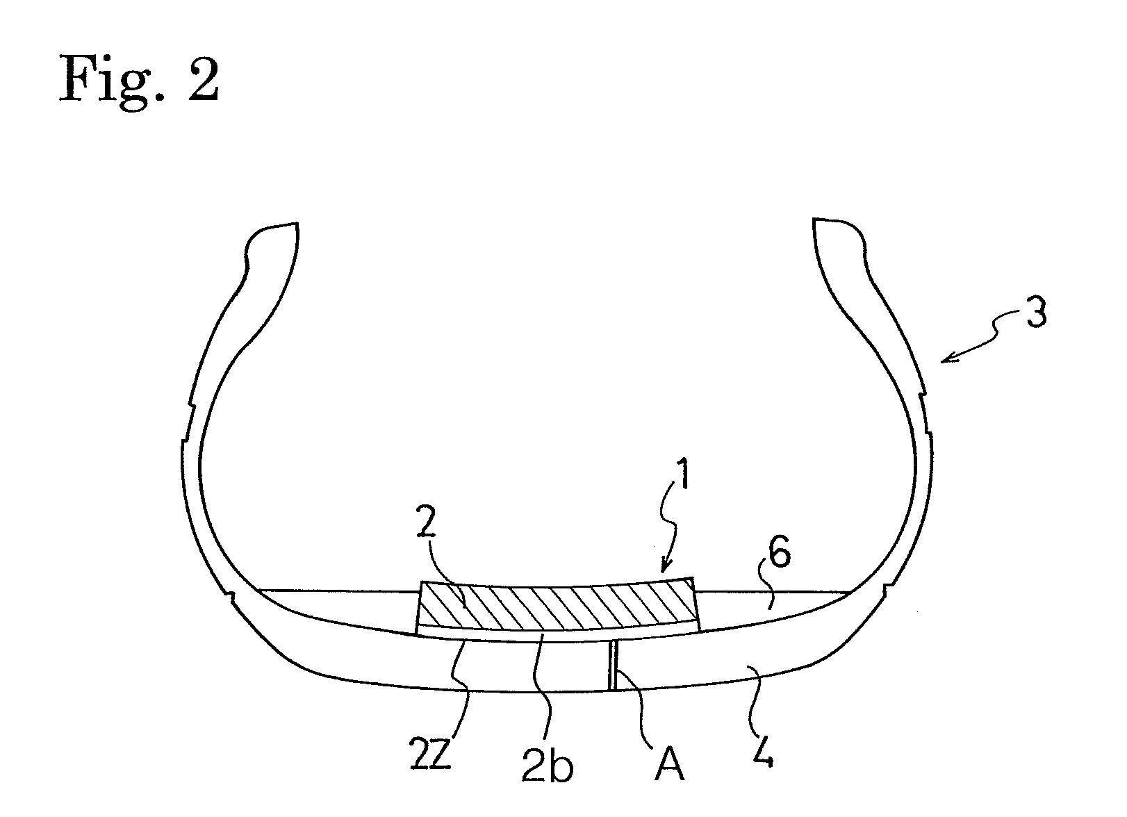
[0020]In the above-described tire noise reduction device of the present invention, the multiple continuous grooves, which are extending see-through regions, are arranged side by side in the tire circumferential direction in the outer peripheral surface of the noise absorbing member. The groove edge-to-edge distance between each adjacent two of the continuous grooves in the tire circumferential direction is set to 2 mm to 40 mm. The largest see-through cross-sectional area of each continuous groove is set to 20 mm2 to 100 mm2. Thereby, these continuous grooves traverse the noise absorbing member in the width direction between the outer peripheral surface of the noise absorbing member and the inner surface of the tire tread portion inner surface. Additionally, continuous spaces are formed at short intervals in the tire circumferential direction. Thus, wherever a through hole is formed in the tread portion, a liquid tire sealant poured through an air injection valve is smoothly guided into and seals the through hole. Moreover, each continuous groove has the areal groove bottom. Accordingly, even when the noise absorbing member is repeatedly flexed, a stress is not concentrated on the groove bottom of the continuous groove. Thus, the durability of the noise absorbing member is retained.

Problems solved by technology

This cavity resonance sound is known to make a vehicle occupant uncomfortable when transmitted into the vehicle compartment.
However, the aforementioned tire that has the noise absorbing member disposed on the inner surface of the tread portion has a problem that the tire sealing operation cannot be performed smoothly even when a liquid tire sealant 6 is poured into a cavity of a tire 3 as shown in FIG. 18.
This makes the operation of sealing a hole of the punctured tire more time-consuming.

Method used


Image

  • Tire noise reduction device
  • Tire noise reduction device
  • Tire noise reduction device

Examples


examples

[0069]Eight types of pneumatic tires (Examples 1 to 5 and Comparative Examples 1 to 3) were prepared. Each of the pneumatic tires had a tire size of 215 / 60R16 and included a noise absorbing member attached to the inner surface of a tire tread portion all around, in common. The noise absorbing member was made of a foamed polyurethane (having an apparent density of 18 kg / m3) and had a width of 180 mm and a thickness of 20 mm. However, the noise absorbing member of each pneumatic tire had a different form from those of the others. In the tire of Comparative Example 1, a tire noise reduction device included the noise absorbing member with a flat outer peripheral surface as shown in FIG. 18. In each tire of Examples 1, 2 and Comparative Examples 2, 3, the noise absorbing member included multiple straight continuous grooves having rectangular cross-sections in the outer peripheral surface thereof in common. However, the tires of Examples 1, 2 and Comparative Examples 2, 3 differed from on...


PUM


Abstract

A tire noise reduction device includes at least one noise absorbing member made of a porous material. The noise absorbing member is attached to the inner surface of the tire tread portion. The noise absorbing member includes multiple continuous grooves arranged side by side in a tire circumferential direction in the outer peripheral surface of the noise absorbing member. Each of the continuous grooves has an areal groove bottom and forms see-through regions in the width direction of the noise absorbing member. A groove edge-to-edge distance between each adjacent two of the continuous grooves in the tire circumferential direction is 2 mm to 40 mm. A largest see-through cross-sectional area of each continuous groove is 20 mm2 to 100 mm2.

Description

BACKGROUND OF THE INVENTION[0001]1. Field of the Invention[0002]The present invention relates to a tire noise reduction device. More specifically, the present invention relates to a tire noise reduction device which allows rapid and reliable tire sealing when a pneumatic tire runs over a nail or the like and is punctured, without deteriorating the durability of a noise absorbing member attached to the inner surface of a tread portion of the tire.[0003]2. Description of the Related Art[0004]A resonance sound is generated in a pneumatic tire due to the vibration of the air in a tire cavity during running. This cavity resonance sound is known to make a vehicle occupant uncomfortable when transmitted into the vehicle compartment. Conventionally, in order to reduce such a cavity resonance noise generated in the tire cavity portion, it is known to dispose a noise absorbing member made of a porous material on the inner surface of a tread portion (see, for example, International Publication...

Claims


Application Information

Patent Timeline
Patent Type & Authority Patents(United States)
IPC IPC(8): B60C5/00B60C19/00
CPCB60C19/002Y10T152/10054Y10T152/10036
Inventor TANNO, ATSUSHI
Owner THE YOKOHAMA RUBBER CO LTD
Why Eureka
Try Eureka