Operating method for a sensor and a control facility communicating with the sensor

a technology of control facility and sensor, which is applied in the direction of liquid/fluent solid measurement, instruments, nuclear elements, etc., can solve the problem of no longer being able to predict the delay of the program sequence, and achieve the effect of minimizing the time of program code and computation

Inactive Publication Date: 2012-03-20
SIEMENS AG
View PDF6 Cites 175 Cited by
  • Summary
  • Abstract
  • Description
  • Claims
  • Application Information

AI Technical Summary

Benefits of technology

[0016]The operating methods allow program code and computation time to be minimized in the control facility. It is also no longer possible for unpredicted delays in the program sequence in the control facility to prevent test mode of the sensor being reset. The data to be transmitted from the control facility to the sensor is also minimized.

Problems solved by technology

It is also no longer possible for unpredicted delays in the program sequence in the control facility to prevent test mode of the sensor being reset.

Method used


Image

  • Operating method for a sensor and a control facility communicating with the sensor
  • Operating method for a sensor and a control facility communicating with the sensor
  • Operating method for a sensor and a control facility communicating with the sensor

Examples


Embodiment Construction

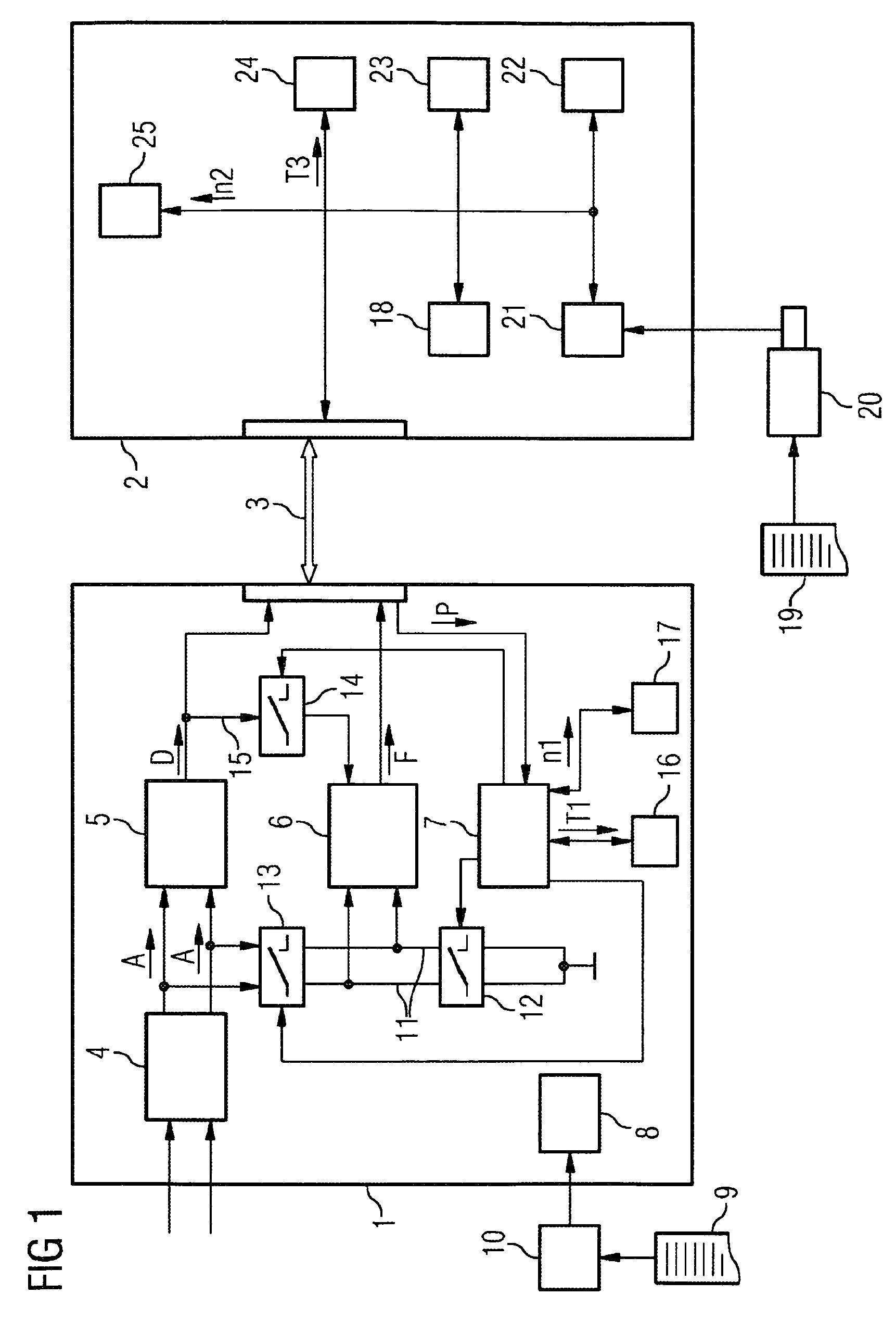
[0026]According to FIG. 1 a sensor 1 and a control facility 2 can communicate with one another by way of a data channel 3. The data channel 3 can be a single-core or multi-core cable (copper, coaxial, optical waveguide) or a cable-free connection (wireless, infrared, etc.) for example.

[0027]According to FIG. 1 the sensor 1 has a detection facility 4, an evaluation facility 5, a monitoring facility 6 and a manipulation facility 7. It can also have an intelligent unit 8, for example a microprocessor or a microcontroller.

[0028]The sensor 1 can have discrete structural elements. It is preferably configured as an ASIC.

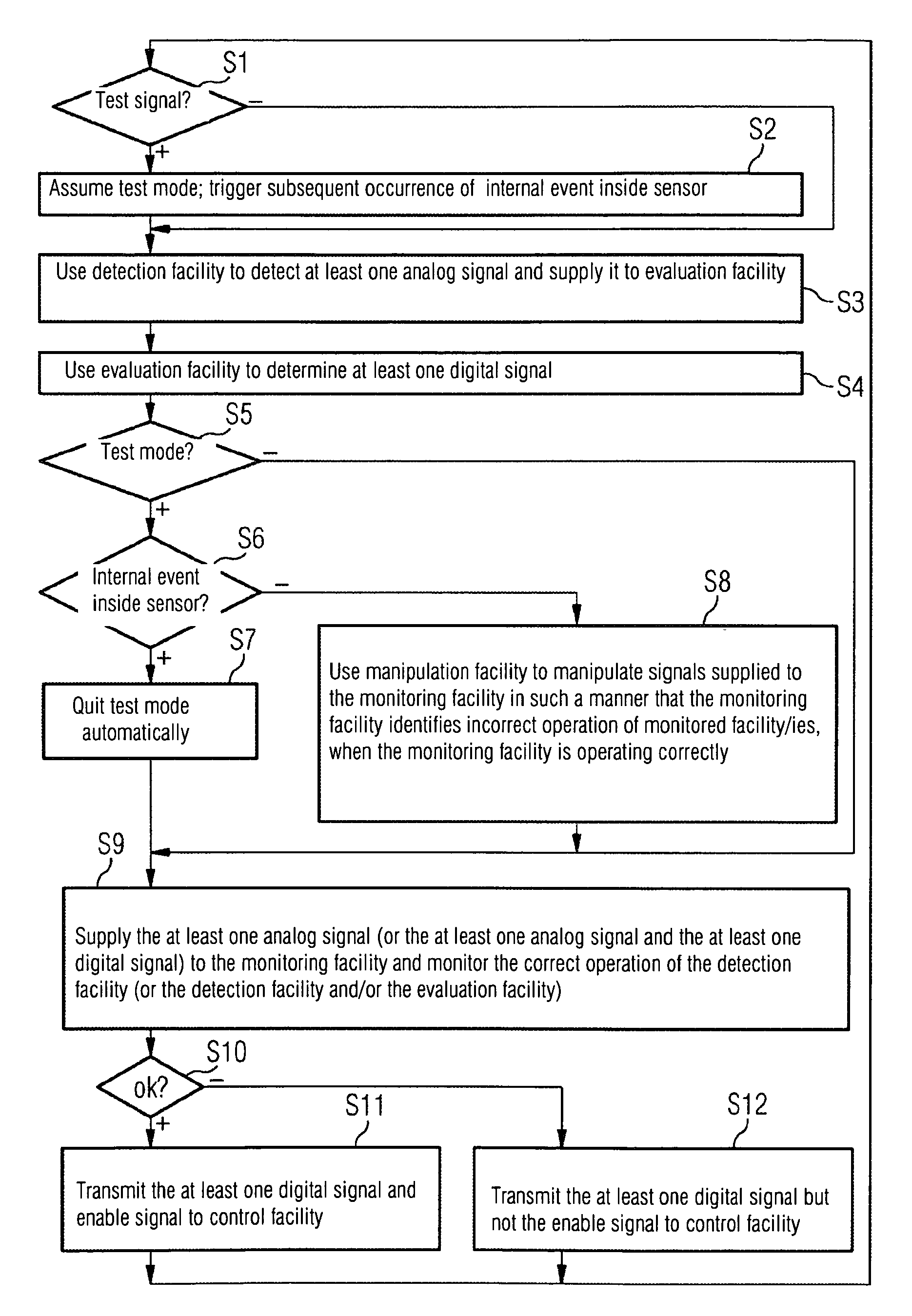
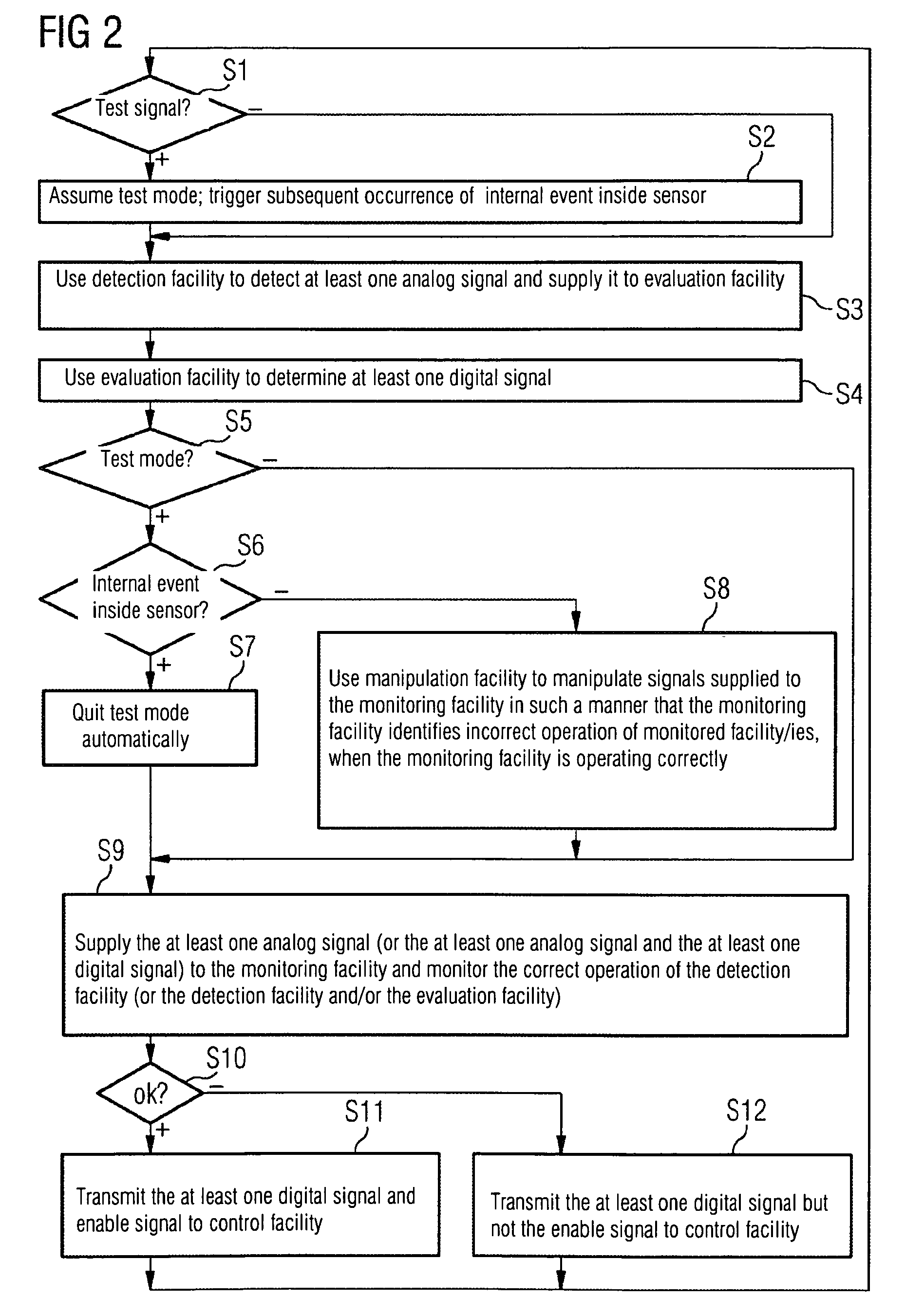
[0029]If the intelligent unit 8 is not present, the sensor 1 is configured based on a corresponding circuit-related embodiment in such a manner that it executes an operating method, which is described in more detail below in conjunction with FIGS. 2 to 6. If the sensor 1 has the intelligent unit 8, the intelligent unit 8 executes a computer program 9. In this instance the s...


PUM


Abstract

A sensor has a detection device and an evaluation device to detect an analog signal, to determine a digital signal and to transmit the digital signal to a control device outside the sensor. The analog signal and / or the digital signal is supplied to a monitoring device of the sensor. An enable signal is transmitted to the control device only if the device being monitored is operating correctly. In a normal mode, the control device processes the digital signal further. Otherwise, it deems the transmitted digital signal to be defective and outputs a message using a malfunction of the sensor. On account of the transmission of the test signal, the sensor assumes a test mode in which it manipulates the signals which are supplied to the monitoring device in such that the monitoring device detects that the device being monitored is not operating correctly. In the test mode, the control device outputs a message using a malfunction of the sensor if the enable signal is transmitted to it in addition to each.

Description

CROSS REFERENCE TO RELATED APPLICATIONS[0001]This application is the US National Stage of International Application No. PCT / EP2007 / 052540 filed Mar. 16, 2007, and claims the benefit thereof. The International Application claims the benefits of German application No. 10 2006 023 213.5 DE filed May 17, 2006. Both of the applications are incorporated by reference herein in their entirety.FIELD OF INVENTION[0002]The present invention relates to an operating method for a sensor and a control facility communicating with the sensor.BACKGROUND OF INVENTION[0003]Such operating methods are known from DE-A-102 44 583 for example.[0004]With the known operating methods for a sensor the sensor uses a detection facility to detect at least one analog signal, uses the at least one analog signal to determine at least one digital signal by means of an evaluation facility and transmits the at least one digital signal to a control facility outside the sensor. The at least one analog signal is also suppl...

Claims


Application Information

Patent Timeline
Patent Type & Authority Patents(United States)
IPC IPC(8): G06F11/30
CPCG01D5/24457
Inventor SIESS, RAINER
Owner SIEMENS AG
Why Eureka
Try Eureka